Longitudinal Component Properties of Circularly Polarized Terahertz Vortex Beams
 Miao Wang
 Xinke Wang
 Peng Han
 Wenfeng Sun
  Yan Zhang
- Department of Physics, Beijing Key Lab for Metamaterials and Devices, Capital Normal University, Beijing, China
A circularly polarized vortex beam possesses similar focusing properties as a radially polarized beam. This type of beam is highly valuable for developing optical manufacturing technology, microscopy, and particle manipulation. In this work, a left-hand circularly polarized terahertz (THz) vortex beam (CPTVB) is generated by utilizing a THz quarter wave plate and a spiral phase plate. Focusing properties of its longitudinal component Ez are detailedly discussed on the simulation and experiment. With reducing the F-number of the THz beam and comparing with a transverse component Ex of a general circularly polarized THz beam, the simulation results show that the focal spot size and intensity of its Ez component can reach 87 and 50% of Ex under a same focusing condition. In addition, the experimental results still demonstrate that the left-hand CPTVB can always maintain fine Ez focusing properties in a broad bandwidth, which manifest the feasibility of this class of THz beams.
Introduction
As the maturation of terahertz (THz) technology, this kinds of far-infrared sensing and imaging methods have gradually presented powerful application values in many research and industrial fields [1, 2]. Recently, investigations and applications of THz special beams have obviously become a hot spot and attracted growing attention. Taking advantages of their distinctive diffraction characteristics, all kinds of special beams have been successfully applied in THz imaging [3], THz communications [4], electron acceleration [5], and so on. In 2006, Zhan Q. W. theoretically proposed that the longitudinal electric field component of a circularly polarized vortex beam is analogous to that of a radially polarized beam, which possesses a sharper focal spot [6]. In 2016, our report experimentally verified the properties of this kind of optical beam in the THz waveband and pointed out its application prospects in THz microscopy and particle acceleration [7]. In 2017, Minasyan A. et. al designed a space-variant birefringent slab to achieve a circularly polarized THz vortex beam (CPTVB) [8]. In 2019, Sirenko A. A. et. al demonstrated that modified broadband circularly polarized THz vortices can be utilized as a spectroscopic probe of magnetism [9]. In 2021, Sobhani H. theoretically discussed the creation of a THz pulse carrying orbital angular momentum via beating twisted laser pulses in the plasma [10]. Apparently, the generation methods and characteristics of CPTVBs have gained more and more attention. Compared to a radially polarized THz beam, a CPTVB can be more easily produced and modulated by using a THz quarter wave plate (TQWP) and a spiral phase plate (SPP). Therefore, a further study on longitudinal component features of a CPTVB is valuable for improving the performances of current THz systems.
In this paper, we compared focusing properties of the longitudinal component of a CPTVB and the transverse component of a general circularly polarized THz beam on the simulation and experiment. Under different focusing conditions, evolutions of their focal spots are presented and analyzed. Besides, the dispersive characteristics of the longitudinal component of a CPTVB produced by using a TQWP and a SPP are also observed and discussed.
Simulation
Firstly, we present and analyze the field distributions of CPTVBs on the simulation. Figure 1 gives the schematic diagram of a CPTVB generated by a TQWP and a SPP. The incident THz wave with a x-linear polarization illuminates a TQWP to possess a circular polarization. Then, the circularly polarized THz beam carries a spiral wave front after passing through a SPP. To generate a strong longitudinal electric field component, a high resistivity silicon (Si) lens is adopted to focus the THz beam. Here, a modified Richards-Wolf integration algorithm is utilized to simulate vector THz field components [11]. In the high-aperture aplanatic focusing system, the focal spot is located at a sufficient distance away from the aperture. Then, vector components of a THz vortex beam in a homogeneous dielectric medium near the focus can be written as
where
where m is the topological charge of the SPP, sgn (p) is the sign of the input polarization,
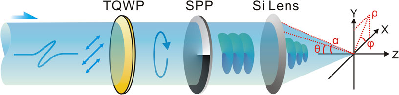
FIGURE 1. Schematic diagram of a circularly polarized THz vortex beam (CPTVB). TQWP: THz quarter wave plate; SPP: spiral phase plate.
In the initial simulation, these parameters are set as
where
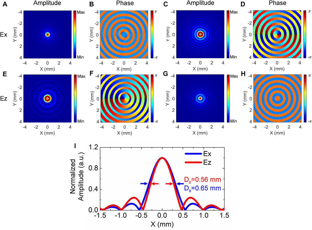
FIGURE 2. (A,E) Amplitude and (B,F) phase patterns of Ex and Ez for a left-hand CPTVB with m = 0. (C,G) Amplitude and (D,H) phase distributions of Ex and Ez for a left-hand CPTVB with m = −1. (I) Normalized amplitude profile curves of Ex with m = 0 and Ez with m = −1. These curves are extracted from (A) and (G), respectively.
Then, the THz beam can be considered as a linear superposition of the
In addition, it should be noted that a right-hand circularly polarized THz beam can be also used to generate a sharp real focus of Ez in a similar manner. When a spiral phase modulation with m = 1 is loaded on a THz beam with a right-hand circular polarization, the constructive interference of Ez is fulfilled on the optical axis and a focal spot of Ez is formed. However, Ez suffers from destructive interference when a spiral phase modulation with m = −1 is loaded on a right-hand circularly polarized THz beam. In that case, the Ez component will present a vortex pattern with a topological charge of −2. The related discussions have been reported in our previous work [7].
The most important property of a converging radially polarized beam is that the focal spot size of its Ez component is smaller than that of the Ex component of a general focused beam with a same F-number, which is very valuable for optical microscopy [13] and particle acceleration [5]. Herein, we compare the focal spot sizes of Ez with m = −1 and Ex with m = 0 for left-hand CPTVBs. The amplitude profiles of Ez with m = −1 and Ex with m = 0 are separately extracted along the x axis from Figures 2A,G. Their normalized curves are plotted and compared, as shown in Figure 2I. The full width half maximum (FWHM) Dz and Dx of Ez and Ex are marked by red and blue arrows, which are 0.56 and 0.65 mm, respectively. It clearly manifests that a CPTVB can be utilized to form a smaller focal spot.
To further analyze Ez properties of a CPTVB, the focal length f is varied from 10 to 80 mm and other parameters are fixed in the simulation. The amplitude patterns of Ex with m = 0 and Ez with m = −1 of left-hand CPTVBs are simulated and their amplitude profiles are extracted along the x axis. Figures 3A,B exhibit the amplitude profile distributions of Ex and Ez along different F-numbers. Obviously, their common points are that the focal spot sizes of Ex and Ez monotonically enlarge and their intensities progressively attenuate with increasing the F-number. To more intuitively observe the variation tendencies of their focal spots, the FWHMs Dx and Dz of Ex and Ez are extracted and plotted in Figure 3C. Dx and Dz vary from 0.40 mm and 0.35 mm to 2.28 mm and 2.05 mm with adjusting the F-number from 0.5 to 4. Meanwhile, it is apparent that Dz is always smaller than Dx with different F-numbers. In addition, the ratio of Dz to Dx is also calculated and exhibited in Figure 3E, which alters from 0.87 to 0.90 with changing the F-number from 0.5 to 4. It can be found that the ratio almost remains unchanged with decreasing the F-number from 4 to 1.5 and it sharply reduces when the F-number is less than 1.5. Besides, intensities of Ex and Ez with different F-numbers are also compared and analyzed. Figure 3D gives the variations of the Ex and Ez amplitude peaks at x = 0 with changing the F-number. It should be noted that both Ex and Ez amplitudes are normalized to the Ex amplitude peak. It can be observed that both Ex and Ez amplitudes monotonically enhance with decreasing the F-number and the evolution trend of Ez is more pronounced when the F-number is less than 1.5. The ratio |Ez|/|Ex| of the Ex and Ez amplitudes is also calculated and shown in Figure 3F, which shows that the proportion of Ez is more and more significant with reducing the F-number and can approach 50% with the F-number of 0.5. According to these simulation results, it indicates that a focusing condition with a smaller F-number is essential for acquiring a Ez focal spot with a smaller size and a higher intensity.
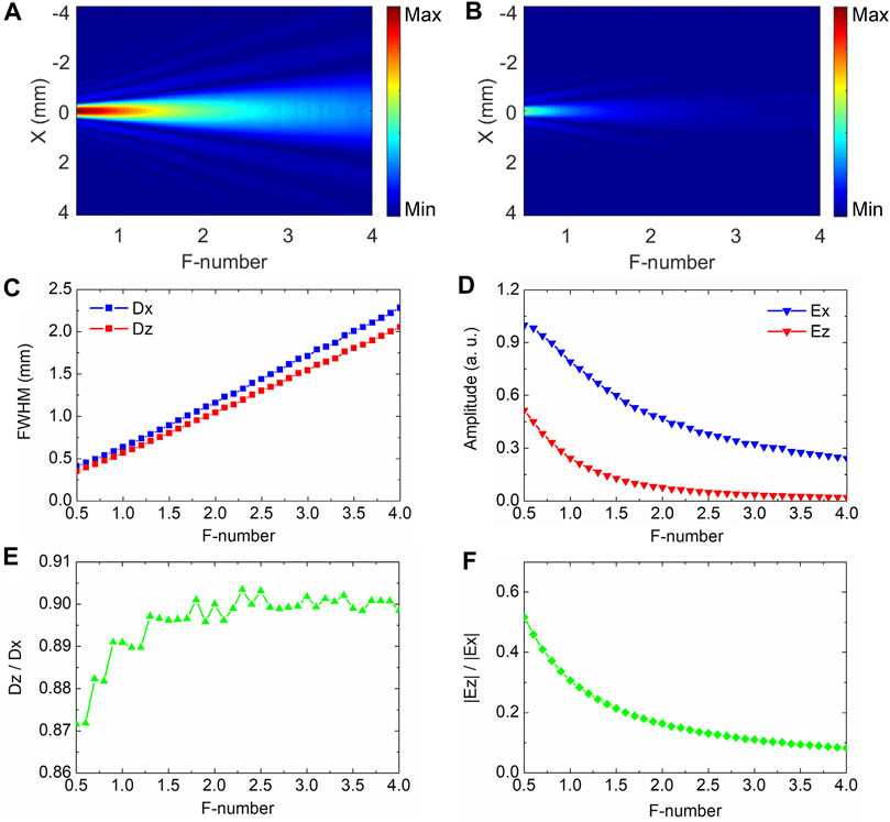
FIGURE 3. Variations of amplitude profiles with different F-numbers for (A) Ex with m = 0 and (B) Ez with m = −1 of left-hand CPTVBs. (C) and (E) give the variation tendencies of the FWHMs Dx and Dz of Ex and Ez and their ratio Dz/Dx with varying the F-number. (D) and (F) exhibit the evolution trends of Ex and Ez amplitude peaks and their ratio |Ez|/|Ex| with adjusting the F-number.
Experiment
On the experiment, CPTVBs are also achieved and analyzed. A THz focal-plane imaging system is applied to characterize the features of CPTVBs, as shown in Figure 4. A Spectra-Physics femtosecond laser amplifier (800 nm central wavelength, 35 fs pulse duration, 1 W average power, and 1 kHz repetition ratio) is used as the light source. The laser pulse is divided into the pump and probe beams by a half wave plate (HWP) and a polarization beam splitter (PBS) for exciting and detecting the THz wave. After passing through a motorized linear stage, the pump beam with a 990 mW average power is expanded by a concave lens L1 with a 50 mm focal length and is guided to illuminate a <110> ZnTe crystal with a 2 mm thickness. Then, the THz radiation with a linear polarization is generated by the optical rectification effect [14]. An axis-off parabolic mirror (PM) with a 100 mm focal length is utilized to collimate the THz beam. Herein, the diameter of the THz beam is approximately 20 mm. After successively transmitting through a TQWP, a SPP and a Si lens, a converging left-hand CPTVB is formed and is incident into the sensor crystal (SC). On the path of the probe beam, the laser pulse with a 10 mW average power is sequentially expanded and collimated by concave and convex lenses (L2 and L3) with focal lengths of 50 and 150 mm. The diameter of the probe beam roughly reaches 30 mm. A polarizer (P) is used to ensure the probe polarization and the probe beam is reflected onto the SC. In the SC, the two-dimensional THz information is modulated on the probe polarization by the linear electro-optic effect [15]. The probe beam carrying the THz information is reflected by the SC and a 50/50 non-polarizing beam splitter in sequence and is guided into the imaging module of the system, which is constituted of a lens group (L4 and L5), a quarter wave plate (QWP), a Wollaston prism (WP), and a CCD camera with a 4 Hz frame rate. The imaging module is applied to capture the image of the probe beam on the SC. A mechanical chopper is mounted in the pump beam to modulate the output frequency of the THz pulse and is synchronously controlled with the CCD camera. Dynamics subtraction and balanced electro-optic detection methods are adopted to remove the background intensity of the probe beam [16, 17] and a two-dimensional THz image is accurately extracted. By continuously adjusting the time delay between the pump and probe beams, a series of THz temporal images are measured and the Fourier transformation is operated on each pixel to acquire the THz spectral information. To suppress the background noise of the system, 25 frames are averaged at each temporal scan point. In this system, the effective imaging area is 12 mm × 12 mm and the size of a pixel is 57 μm.
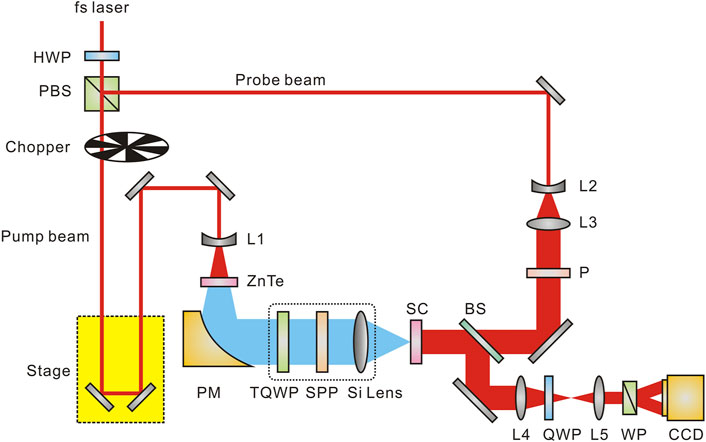
FIGURE 4. Schematic diagram of a THz focal-plane imaging system.
To characterize the different polarization components of the THz beam, the SCs with various crystalline orientations are carefully selected. In the measurement, the probe polarization is always fixed as the horizontal direction. A <110> ZnTe with a 1 mm thickness is chosen to measure the transverse electric field Ex of the THz beam. To maximize the detection efficiency, the angle between the <001> direction of the crystal and the probe polarization is set as 0°. A <100> ZnTe with a 1 mm thickness is selected to acquire the longitudinal electric field Ez of the THz beam. The <010> direction of the crystal is tuned to 45° with respect to the probe polarization to optimize the detection efficiency [7].
To achieve a left-hand circularly polarized THz beam, a quartz TQWP (TYDEX Company, Russia) with a 400 μm central wavelength is applied. A Teflon SPP with a topological charge of −1 and a 400 μm central wavelength is used to impart a spiral phase modulation on the THz beam. Three Si lenses with focal lengths of 20 mm, 30 mm, 50 mm are separately picked up to produce the converging CPTVBs for comparing the features of Ez with different focusing conditions. On the focal plane, the Ex and Ez components of the left-hand CPTVBs are measured and analyzed by using the imaging system.
Figure 5 exhibits the comparison of the Ex and Ez components under different focusing conditions. Figures 5A,D,G give the amplitude distributions of the focal spots with f = 20 mm, 30 mm, 50 mm at 0.75 THz for Ex with m = 0 of left-hand CPTVBs. Figures 5B,E,H show the amplitude patterns of Ez with three different focal lengths at 0.75 THz on the focal plane for left-hand CPTVBs with m = −1. Obviously, the focal spot sizes of Ex and Ez are gradually magnified with increasing f. For clarity, their corresponding amplitude profile curves are extracted along the x axis. The normalized curves of Ex and Ez with f = 20 mm, 30 mm, 50 mm are plotted and compared, as shown in Figures 5C,F,I. When the focal length of the Si lens is 20 mm, the FWHMs Dx and Dz of Ex and Ez are 0.87 and 0.61 mm, respectively. When f is adjusted as 30 mm, Dx and Dz are 1.22 and 1.02 mm. When f is varied as 50 mm, both Dx and Dz are almost equal to 2.32 mm. Simultaneously, the side-lobes of Ez becomes more striking. Experimental results are mainly consistent with the simulation. When a CPTVB is more tightly focused, the Ez component with a smaller focal spot is formed. In addition, the focal spot size of Ez is always less than that of Ex. Some slight deviations between the experimental and simulation results are mainly attributed to the integral effect of the 1 mm-thick SCs [18] and other measurement errors. Besides, the ratios of Dz/Dx and |Ez|/|Ex| are also calculated and exhibited in Figures 5J,K, which presents similar tendencies as the simulation results.
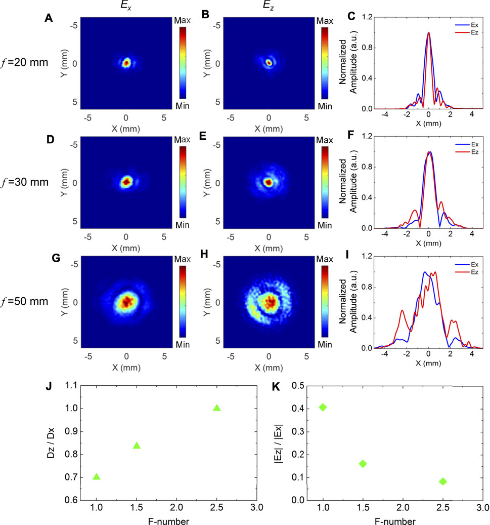
FIGURE 5. Comparison of the transverse and longitudinal components under different focusing conditions. (A), (D), (G) and (B), (E), (H) separately present the amplitude distributions of the focal spots with focal lengths of 20 mm, 30 mm, 50 mm at 0.75 THz for Ex with m = 0 and Ez with m = −1 of left-hand CPTVBs. (C), (F), (I) give their corresponding normalized amplitude profile curves along the x axis (J) and (K) show the ratios of Dz/Dx and |Ez|/|Ex| with varying the F-number, respectively.
Moreover, the dispersive characteristics of the focal spots with different focal lengths are also checked for Ez with m = −1 of left-hand CPTVBs. From the measurement results of Ez, each spectral amplitude profile curves are extracted along the x axis. Figures 6A–C present the amplitude profile distributions of Ez with f = 20 mm, 30 mm, and 50 mm along different frequencies. In Figures 6A,B, it can be seen that Ez always possesses a clear real focus from 0.5 THz to 1.0 THz. With f = 50 mm, the focal spot gets blurred at frequencies away from 0.75 THz due to the weaker Ez component, as shown in Figure 6C. It manifests that a CPTVB can generate a fine converging Ez component with a broad bandwidth, although the modulation effects of the TQWP and SPP are the most perfect at the central wavelength.
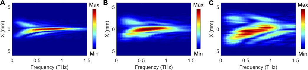
FIGURE 6. Dispersive characteristics of the focal spots with f = 20 mm (A), 30 mm (B), and 50 mm (C) for the Ez components with m = −1 of left-hand CPTVBs.
Conclusion
In conclusion, the focusing properties of the Ez component are analyzed in detail for a converging CPTVB. The simulation and experimental results show that a CPTVB can form a real Ez focus when its topological charge is carefully adjusted. With reducing the F-number, the Ez component can get a sharper focal spot and a higher intensity. Particularly, the focal spot size of Ez is always less than that of the Ex component of a general circularly polarized THz beam with the same F-number. In addition, Ez can remain a fine focusing effect in a broad bandwidth for a CPTVB generated by a TQWP and a SPP. This work provides an effective avenue to produce a longitudinal THz polarization component with a smaller size and a stronger intensity. It can be expected that this class of CPTVBs will exhibit important application values for improving current THz inspection systems.
Data Availability Statement
The original contributions presented in the study are included in the article/Supplementary Material, further inquiries can be directed to the corresponding author.
Author Contributions
MW performed the research and wrote the paper. XW and YZ proposed the concept. PH, WS, SF, and JY supervised the project. All authors discussed the results and co-wrote the article.
Funding
This research was supported by the National Natural Science Foundation of China (61735002, 11774243, 11774246, and 11404224), Youth Innovative Research Team of Capital Normal University (008/20530290053, 008/19530050146, 008/18530500155), Connotative Development Foundation for Distinguished Young Talents in Capital Normal University (2055105), and Capacity Building for Sci-Tech Innovation-Fundamental Scientific Research Funds (008/20530290072, 008/19530050180, 025185305000/142).
Conflict of Interest
The authors declare that the research was conducted in the absence of any commercial or financial relationships that could be construed as a potential conflict of interest.
Publisher’s Note
All claims expressed in this article are solely those of the authors and do not necessarily represent those of their affiliated organizations, or those of the publisher, the editors and the reviewers. Any product that may be evaluated in this article, or claim that may be made by its manufacturer, is not guaranteed or endorsed by the publisher.
References
1. Tonouchi M. Cutting-Edge Terahertz Technology. Nat Photon (2007) 1:97–105. doi:10.1038/nphoton.2007.3
2. Guerboukha H, Nallappan K, Skorobogatiy M. Toward Real-Time Terahertz Imaging. Adv Opt Photon (2018) 10:843–938. doi:10.1364/AOP.10.000843
3. Bitman A, Moshe I, Zalevsky Z. Improving Depth-Of Field in Broadband THz Beams Using Nondiffractive Bessel Beams. Opt Lett (2012) 37:4164–6. doi:10.1364/OL.37.004164
4. Hui X, Zheng S, Chen Y, Hu Y, Jin X, Chi H, et al. Multiplexed Millimeter Wave Communication with Dual Orbital Angular Momentum (OAM) Mode Antennas. Sci Rep (2015) 5:10148. doi:10.1038/srep10148
5. Nanni EA, Huang WR, Hong K-H, Ravi K, Fallahi A, Moriena G, et al. Terahertz-Driven Linear Electron Acceleration. Nat Commun (2015) 6:8486. doi:10.1038/ncomms9486
6. Zhan Q. Properties of Circularly Polarized Vortex Beams. Opt Lett (2006) 31:867–9. doi:10.1364/OL.31.000867
7. Wang X, Shi J, Sun W, Feng S, Han P, Ye J, et al. Longitudinal Field Characterization of Converging Terahertz Vortices with Linear and Circular Polarizations. Opt Express (2016) 24:7178–90. doi:10.1364/OE.24.007178
8. Minasyan A, Trovato C, Degert J, Freysz E, Brasselet E, Abraham E. Geometric Phase Shaping of Terahertz Vortex Beams. Opt Lett (2017) 42:41–4. doi:10.1364/OL.42.000041
9. Sirenko AA, Marsik P, Bernhard C, Stanislavchuk TN, Kiryukhin V, Cheong S-W. Terahertz Vortex Beam as a Spectroscopic Probe of Magnetic Excitations. Phys Rev Lett (2019) 122:237401. doi:10.1103/PhysRevLett.122.237401
10. Sobhani H. Creation of Tunable Longitudinally Polarized Terahertz Pulse Carrying Orbital Angular Momentum. Phys Lett A (2021) 387:127011. doi:10.1016/j.physleta.2020.127011
11. Khonina SN, Kazanskiy NL, Volotovsky SG. Vortex Phase Transmission Function as a Factor to Reduce the Focal Spot of High-Aperture Focusing System. J Mod Opt (2011) 58:748–60. doi:10.1080/09500340.2011.568710
12. Youngworth KS, Brown TG. Focusing of High Numerical Aperture Cylindrical-Vector Beams. Opt Express (2000) 7:77–87. doi:10.1364/OE.7.000077
13. Huse N, Schönle A, Hell SW. Z-Polarized Confocal Microscopy. J Biomed Opt (2001) 6:480–4. doi:10.1117/1.1417974
14. Löffler T, Hahn T, Thomson M, Jacob F, Roskos HG. Large-Area Electro-Optic ZnTe Terahertz Emitters. Opt Express (2005) 13:5353–62. doi:10.1364/OPEX.13.005353
15. Wu Q, Litz M, Zhang XC. Broadband Detection Capability of ZnTe Electro‐Optic Field Detectorsfield Detectors. Appl Phys Lett (1996) 68:2924–6. doi:10.1063/1.116356
16. Jiang Z, Xu XG, Zhang X-C. Improvement of Terahertz Imaging with a Dynamic Subtraction Technique. Appl Opt (2000) 39:2982–7. doi:10.1364/AO.39.002982
17. Wang X, Cui Y, Sun W, Ye J, Zhang Y. Terahertz Real-Time Imaging with Balanced Electro-Optic Detection. Opt Commun (2010) 283:4626–32. doi:10.1016/j.optcom.2010.07.010
Keywords: terahertz, circularly polarized vortex beam, longitudinal component, focusing properties, dispersive characteristics
Citation: Wang M, Wang X, Han P, Sun W, Feng S, Ye J and Zhang Y (2021) Longitudinal Component Properties of Circularly Polarized Terahertz Vortex Beams. Front. Phys. 9:736831. doi: 10.3389/fphy.2021.736831
Received: 05 July 2021; Accepted: 18 August 2021;
Published: 31 August 2021.
Edited by:
Yiqi Zhang, Xi’an Jiaotong University, ChinaReviewed by:
Dong Mao, Northwestern Polytechnical University, ChinaTongyi Zhang, Xian Institute of Optics and Precision Mechanics (CAS), China
Zuanming Jin, University of Shanghai for Science and Technology, China
Copyright © 2021 Wang, Wang, Han, Sun, Feng, Ye and Zhang. This is an open-access article distributed under the terms of the Creative Commons Attribution License (CC BY). The use, distribution or reproduction in other forums is permitted, provided the original author(s) and the copyright owner(s) are credited and that the original publication in this journal is cited, in accordance with accepted academic practice. No use, distribution or reproduction is permitted which does not comply with these terms.
*Correspondence: Xinke Wang, wxk82721@cnu.edu.cn