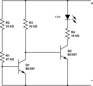
The following post describes a simple low battery indicator circuit by using just two inexpensive NPN transistors. The main feature of this circuit is its very low stand by current consumption.
We can also make a low battery indicator circuit using a 741 IC and a 555 IC, which are no doubt outstanding with their abilities of detecting and indicating low battery voltage thresholds.
However the following post relates yet another similar circuit which is much cheaper and employs just a couple of NPN transistors for producing the required low battery indications.
The main advantage of the proposed two transistor low battery indicator circuit is its very low current consumption compared to the IC counterparts which consume relatively higher currents. A IC 555 would consume around 5mA, a IC741 around 3 mA, while the present circuit would just consume around 1.5mA current.
Thus the present circuit becomes more efficient especially in cases where stand by current consumption tend to become an issue, example suppose in units which depend on low current battery supplies such as a 9V PP3 battery.
Another advantage of this circuit is it’s ability to work even at voltages around 1.5V which gives it a clear edge over the IC based circuits.
As shown in the following circuit diagram, the two transistors are configured as voltage sensor and inverter.
The first transistor on the left senses the threshold voltage level as per the setting of the 47K preset. As long as this transistor conducts, the second transistor on the right is held switched OFF, which also keeps the LED switched OFF.
As soon as the battery voltage falls below the set threshold level, the left transistor is no longer able to conduct.
This situation instantly triggers the right hand side transistor, switching ON the LED.
The LED switches ON and provides the required indications of a low battery warning.

why isn’t the 47k resistor variable?
LikeLike
I want circuit for 3.7v battery…..
LikeLike
I think the circuit drawing is incorrect, showing the base of the first transistor tied to ground. When I changed that and substituted a piezo buzzer for the LED and 10K resistor, I got the circuit to work on my 12 V car battery. Good circuit!
LikeLike
Thanks, for spotting the glitch for me, i will correct it soon.
LikeLike