
Ch Products is a manufacturer of control devices. I’ve been using CH Products since early ’90, and never had problems with them.
They are all plastic, but sound and well manufactured. The components are high quality, the design is sturdy, that’s why they last basically forever.
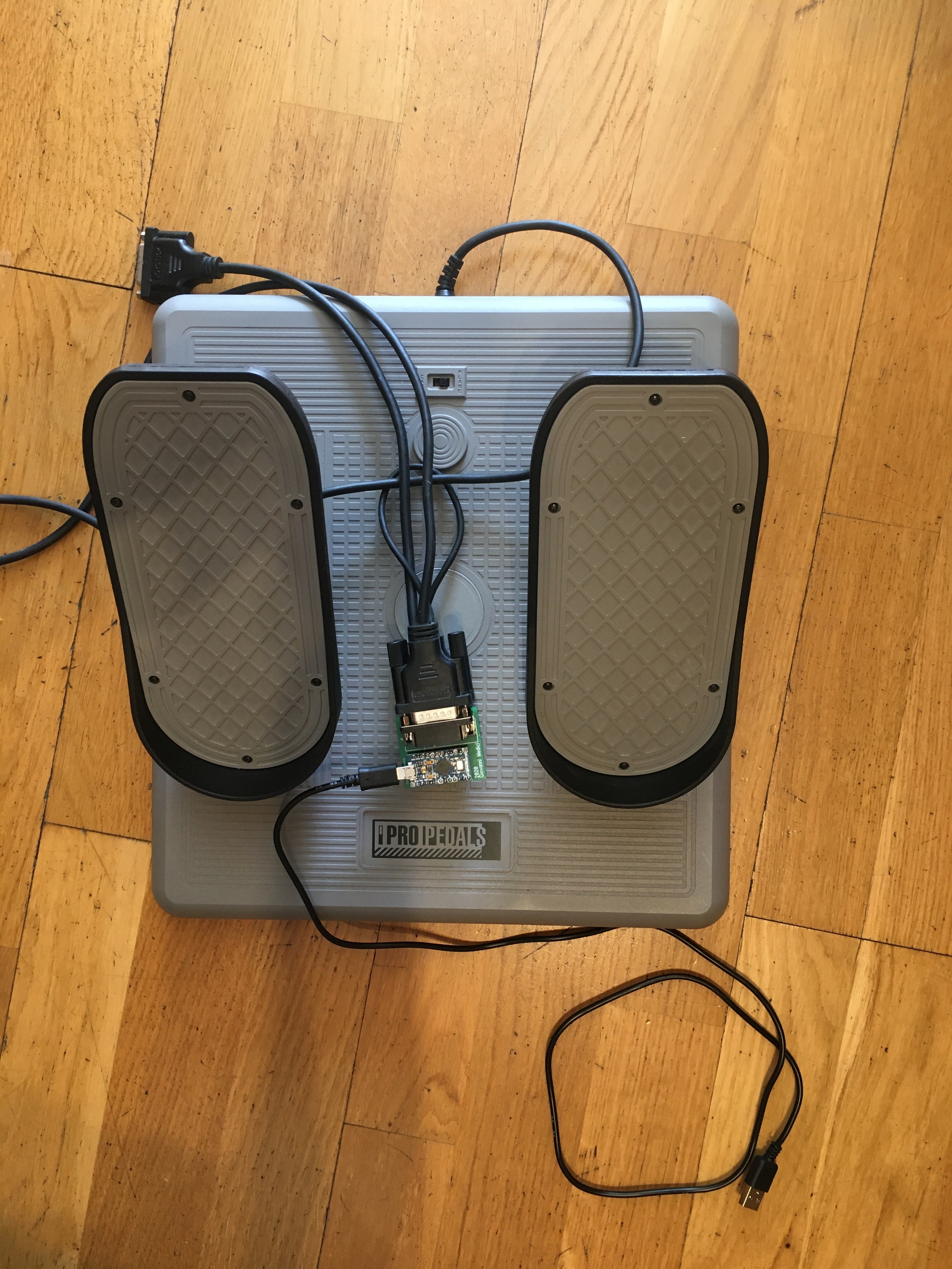
I’ve a set of CH Pro Pedals, with Gameport, but they are somewhat useless in modern computers.
There are Gameport to USB adapters in the market, but they are almost always plug and pray, as back in the Gameport era, the pin wiring was not standardized, so your device may or may not work. In particular for this very case, it is simply impossible for a Gameport to USB adapter to work, as only the Z axis (rudder) OR X and Y (toe brakes) are transmitted through the Gameport wiring (depending on the position of the CAR – PLANE toggle switch).
For this reason I thought of designing and manufacturing a simple, dedicated Gameport to USB adapter.
Design
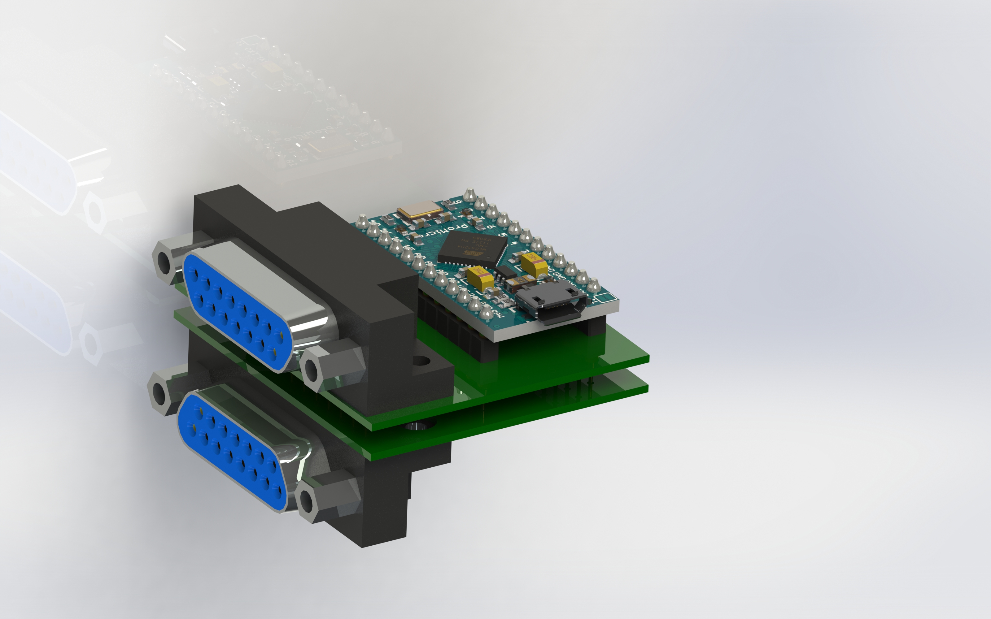
Similarly to the TM Cougar USB adapter, the design is rather simple:
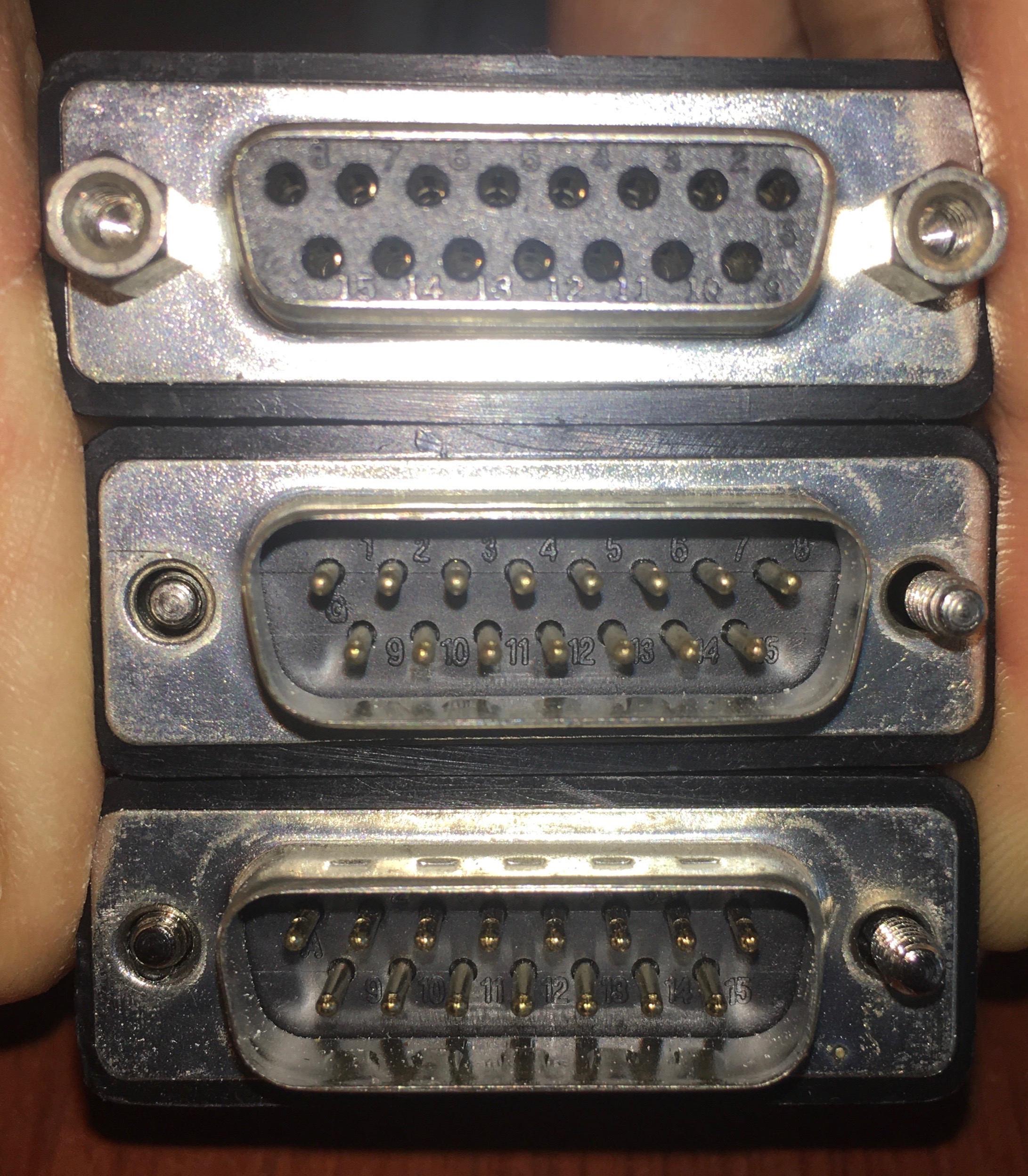
- A connector, namely two DB-15 (with two rows), Female.
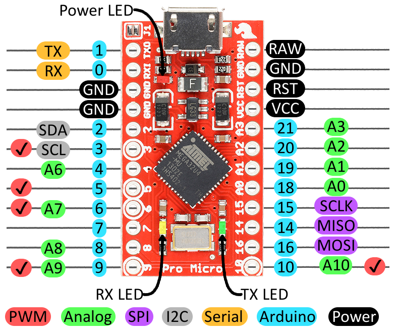
- An Arduino Pro Micro Board.
- A base PCB with the correct wiring between the DA-15 connector, and the Arduino Pro Micro.
- An USB cable.
Luckily enough, back in those days, the wiring scheme of the port was directly written in the device’s manual (thanks to this post of Teensy forum).

The CH Pro Pedals have 3 connectors: 1 marked as Joystick (following CH Product data sheet, C connector, female), 1 marked as Gameport (following CH Product data sheet, B connector, male), and 1 marked as AUX (following CH Product data sheet, A connector, male).
Looking to the diagram of the wiring, depending on the position of the CAR – PLANE toggle switch the VIOLET cable (connected to the Rudder Pot) will or will not transmit to the Gameport Connector . On the other hand, AUX connector (A connector) will always (and only) carry the two pedals potentiometers signals, respectively on pin 3 and 6, that is A3 and A6.
Thus in order to have an external adapter, two DB-15 are needed (one connecting to the Gameport and the other to the AUX), in this way it is possible to have the three axis working at the same time (something that curiously wasn’t possible with the original CH Pro Pedals, at least to my understanding).
The PCB board is rather simple, following the above diagram, it connects the B1,B8,B9,B15 DB15 pins to the VCC of the Arduino Pro Micro, B4,B5,B12,B13 to the GND, and A3, A6, and B11 to A0,A1,A2, Arduino pins, which are ADC capable. I will be using one piece for the Gameport connector (so to connect the Z axis (rudder), and another to connect the AUX connector, so to have the Toe Brakes. As we are dealing with quite long cables, I added three capacitors to each potentiometers the axis to reduce jitter, they are wired to the ground.
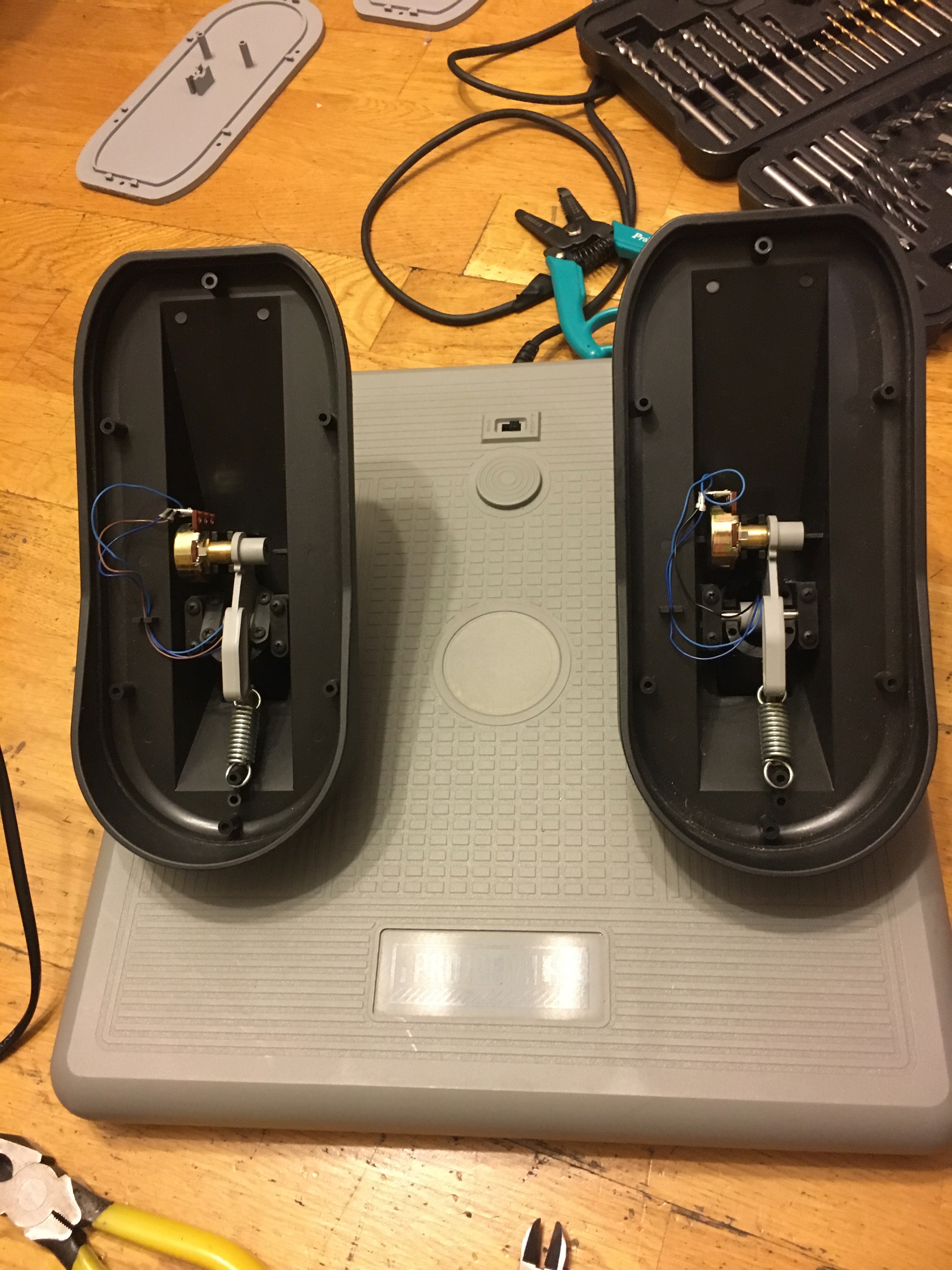
Moreover I rewired the Pedals so to add ground to the three potentiometers. The original wiring, as shown in the pictures, was connecting only VCC and sensing pin to the potentiometers, no ground. As I will use an Arduino Micro, I opted to go for the conventional 3 pin VCC-Sensing-Ground, to wire the potentiometers. To do so I used the Yellow Cable ( I cutted it from the switch and soldered three ground cables to the potentiometers), which connects to the Red cable, and pin 13 of the Gameport Connector.
It is important to remark that the connector I chose, is the FEMALE (so if you look to the connector the first pin is on the first row on the right.

For the sake of completeness, in the diagram that follows, it is reported the Arduino Pro Micro pinout.
CH Pro Pedals disassemble
One dedicated chapter should be dedicated to the Pedals dis/assembly. It is nothing difficoult, but quite counter intuitive to me. To avoid any “surprise”, I think you may find useful these notes …

- First of all, well, disconnect the pedals from the PC.
- Everybody would start by disassembly the base (many screws there), I suggest to disassembly the pedals first, and remove them, as otherwise it will be very difficult to assembly back everything together.
- Unscrew the screws on the light grey part of each pedal.
- Remove the light grey plastic cover of the pedals. It will make you access to the potentiometer screw compartment.
- Gently pull the potentiometer and unplug the connectors.
- Unscrew the pedals from the base.
- Remove the pedals.
- Unscrew the base screws (plenty of them), don’t forget to unscrew the one covered by the Void Warranty sticker.
- It is very likely that the screws which gives the spring back to the pedals will jump out of place.
- You have full access to the pedals internal / movements.
- If you wish to reduce the noise, you may add some plastic grease in the two housing where the rollers slide.


Arduino Code
The code implemented is pretty straightforward, simply providing 3 analogRead and assigning it to the joystick. I used Arduino Joystick Library, as it allows customizing the constructor (I will only save the 3 axis, and drop all the buttons and unneeded axis).
You can also find the most updated version of the code in my Github repository.
// Program used to setup an adapter for Ch Pro Pedals
// Gameport to USB adapter.
//
// Giovanni Medici
// 2020-09-13
//------------------------------------------------------------

#include <Joystick.h>

Joystick_ Joystick(JOYSTICK_DEFAULT_REPORT_ID,
                   JOYSTICK_TYPE_JOYSTICK, 0, 0, // 0 buttons, 0 hatswitches
                   false, false, false, true, true, true, // no x,y,z,Rx,Ry,Rz
                   false, false, false, false, false );         // Rudder, no Throttle, Accelerator and Brake, no Steering


void setup() {
  // Initialize the three axis
  //Joystick.setRxRange(0, 1023);
  //Joystick.setRyRange(0, 1023);
  //Joystick.setRzRange(0, 1023);


  Joystick.begin(false);

}

void loop() {

  //Serial.begin(9600);
  //reduceNoise(A1);
  int sensorA1 = analogRead(A1);
  //reduceNoise(A2);
  int sensorA2 = analogRead(A2);
  //reduceNoise(A3);
  int sensorA3 = analogRead(A3);
  //reduceNoise(A0);
  //int sensorA0 = analogRead(A0);

  Joystick.setRxAxis(1023-sensorA3);
  Joystick.setRyAxis(sensorA2);
  Joystick.setRzAxis(sensorA1);

  Joystick.sendState();
  delay(20);

  //Serial.print(" | A1 XAxisB: ");
  //Serial.print(sensorA1);
  //Serial.print(" | A2 YAxis: ");
  //Serial.print(sensorA2);
  //Serial.print(" | A3 XAxis: ");
  //Serial.println(sensorA3);


}

void reduceNoise(int pinNum)
{
  // This function reduces the noise in the pot
  // (particoularly effective for the Microstick).
  digitalWrite(pinNum, HIGH);
  delay(5);
  digitalWrite(pinNum, LOW);

}
The board
Here the final result, clean output, no noise whatsoever, possibly better than the ordinary CH Pro Pedals USB!


I would be interested in the thing since I have the same product. Who would be willing to make this adapter for me upon payment. Reply on the forum.
Hello
How are you.
Will this aapter work for the ch pro throttle control?
Dear Clifford Johnson, I’d say no. The gameport pinout of the pro throttle will have to cope with 1 axis, three 4 way switches and one hat switch, along with 4 buttons. I’ve never owned one, but if you do, maybe there is some pinout indication in the manual.
Small issue: This links to the wrong Arduino Joystick library. The correct link is https://github.com/MHeironimus/ArduinoJoystickLibrary
Thanks Conrad, I just updated the link to the right Arduino library!
Awesome! I just used this guide (with some modification) to stuff an Arduino into the pedal assembly after I accidentally bought the gameport one on Ebay. Worked like a charm, and was a great introduction to DIY controllers. I’m definitely going to use this for future projects. Thanks for posting it!
Wow Conrad, that’s really great to hear! I’m really happy that the post helped you in some way. Ch Products are really sturdy, I’m sure you will enjoy the pedals!
Thank you for this great solution for old CH pedals, now I can keep using them , as they are really good. One question, tho. Is it possiblento use some other arduino? I cannot find Pro micro, but for eg. Nano is readily available.
Sure, I’d say any arduino would do the job!
– I thought only Pro Micro and Leonardo could do this (simulate joystick analog in)
I have several questions:
– I am not clear how the ground was added. I do not see any yellow cables.
– I plan to use an Arudino Leonardo for this example, so I assume that will work
– I am not sure why there are two DB-15s are required. I only see one USB out but two DB15 and looks like 2 boards made.
– The manual says AUX port is not to be used, but you have used it? in your example
– I have rudders (one) and yoke/switches (two) devices. Should I make two adaptors? and if so, how is the yoke different?
Short version,. I made a mistake and bought these on Ebay. I rather put the USB adaptor together than return these and buy more expensive stuff. I have tons of arduionos, etc. (not a noobie)
Dear Saman,
Thanks for reaching out to me! Long story short, the board itself was a workaround as I didn’t want to change the set up. One may connect directly an arduino pro to the pot signals (possibly adding some capacitor filtering on the line), and is good to go. Two DB-15s are needed to connect to the pedals AUX and GAMEPORT connectors, only one USB is the output. Both connectors are needed due to the fact that in the gameport connector carries the Z-Axis (rudder) signal, while the AUX has the X, and Y axis (actually the brake pedals). Happy to know you are not a nobbie, if you plane to use it for your own utility, I’ll definitely get rid of all the old connectors and connect the arduino directly to the pots.
I’m not sure I get your question about the ground color, but actually GAMEPORT has several grounds.
Talking about the joke, I’ve no idea about how the connections are tied up there, sorry.
thank you for the quick reply. you may email me directly to chat. I would like to cut the cables and make my own adaptor for the Arduino, and even thought I am electric engineer by education, I have little knowledge on how to use the capacitors or the resistors. I assume the capacitor is to smooth out any voltage movements. While the resistor offer pull up or down. I would greatly appreciate at the simplest drawing you can provide. I have dumper wires that can fit directly to the DB15, so I can get all 15 pins to a breadboard. then from the board board to the Adurino. A0,A1,A2,A3 seem find. I an can even put what you need there. I have two devices. the rudder peddles with GamePort, Aux and Joystick DB15 (Male). I also have a CH Pro Yoke, with the same 3 ports. If at all possible reach out as I have time off during the chrismas break and would love to get these to work and not return them for a more expensive item.
Ok, great, I just replied you via mail!
Se eu usar um adaptador gameport para USB somente no modo avião funcionaria ?
It really depends on the wiring of the gameport to USB adapter. I’d say no. Or with limited functionalities, such as only Z Axis (rudder) and no toe brakes. As far as I can tell back in the day there was no “standard” wiring of the gameport, so everything was dealt on the SW side of the driver, obviously creating compatibility problems for something like an “adapter”.
Where did you get the PCB’s made?
Do you have a design PDF?
Are both PCB’s the same?
Dear Andrew,
thanks for your reaching out to me. I sourced the components from Aliexpress, while the PCB I printed them through jlcpcb. Yes the boards are the same, but stacked like a wafer. May I suggest you, if you are going to open the pedals, to directly connect an Arduino board (or any equivalent board) to the pots? The assembly at the end is cumbersome, and the cables ultra-long, therefore the setup is quite prone to interference. In order to understand which cable goes where, the electrical scheme presented in the blog should be fine.
The design image is incomplete as to really take advantage of the (single) board, I had to cut a few connections from the AUX part. So it is pretty much useless if I were to share it with you.
Thanks for your reply.
<
div dir=”ltr”>Just to confirm , all I would require is an Arduino board and USB cab
<
div dir=”ltr”>
Thanks for your suggestions, I now have an Adruiano mini and plan to attach direct to pots as suggested.
<
div dir=”ltr”>Can i clarify cab
Hi going to connect pots to arduino board direct. Can you confirm below:
VCC – blue
GND – yellow
A0 – brown
A1 – black
A2 – red
Pink not used.
Run extra wires to all 3 pots from yellow.
Thanks for your help
Dear Andrew, I’m sorry, I don’t have here the pro pedals to check. The wiring should go as per the rather oldish CH Products connection scheme in the post. Nevertheless if you are going to open the pedals to pass the wires, you’ll easily identify the color codes from each of the three pot.
Hi, I received an old Pro pedals and following your instruction. But, now I have a problem. I am afraid my pedals are not well centered. When I use Game Device Calibration on Windows, center level shows 27674 (42%), and full right rudder gives 65535 (100%). However, when I push left rudder, at around 50% it reaches 0 (0%) and further movement keeps 0. Is it possible to fix it within Arduino sketch?
Hi, I’d suggest to first of all reset to default from the windows device manager (sometimes is not the most straightforward tool, as it may rely on an old calibration), then from the arduino/teensy, I’d add a few lines to print the actual values of the three potentiometers in the console (it will have an impact on the arduino performance, so, when done troubleshooting, I’d suggest remove them). With such lines it will be relatively simple to understand whether you are reaching the physical limits of the potentiometers before reaching the full stroke (full pedal left or right).
A bit of overlay/mis placement is sort of normal I’d say; but having a 0% midway to the full stroke is not ok.
If you saturate the potentiometer so soon, maybe you should open the pedals again and correct the pot position at 50% so to be kind of midway between 0 and full.
Thanks for your reply. I opened it again and there was no mechanical problem. Now I am wondering that a potentiometer itself has a problem. I will replace it and check again.
I replaced the potentiometer taken from another CH joystick, but situation is almost the same. Right rudder is fully functional but left rudder works only around 80% movement.
I suppose the reason would be (1) productional failure of centering pedal, and/or (2) my clone Pro Micro gives more than 5V to the potentiometer. So, my solution is following modification of the sketch;
int sensorA0 = analogRead(A0) – 45 // put offset to adjust center
Joystick.set Rudder(1023-1.0898*sensorA0 +45) // put offset and adjust inclination to get max value at around 80% of movement of rudder
Now, I can use only around 80% of rudder stroke for both, but full rudder is available at both direction. I mean the right rudder reduced functional stroke length, but I can move full left rudder now.
I really appreciate your site and information. If I couldn’t reach it, I would never buy such an old rudder pedals.😉