EP0933103B1 - Wheel suspension for skate boards - Google Patents
Wheel suspension for skate boards Download PDFInfo
- Publication number
- EP0933103B1 EP0933103B1 EP99100627A EP99100627A EP0933103B1 EP 0933103 B1 EP0933103 B1 EP 0933103B1 EP 99100627 A EP99100627 A EP 99100627A EP 99100627 A EP99100627 A EP 99100627A EP 0933103 B1 EP0933103 B1 EP 0933103B1
- Authority
- EP
- European Patent Office
- Prior art keywords
- wheel
- der
- suspension according
- joints
- die
- Prior art date
- Legal status (The legal status is an assumption and is not a legal conclusion. Google has not performed a legal analysis and makes no representation as to the accuracy of the status listed.)
- Expired - Lifetime
Links
Images


Classifications
-
- A—HUMAN NECESSITIES
- A63—SPORTS; GAMES; AMUSEMENTS
- A63C—SKATES; SKIS; ROLLER SKATES; DESIGN OR LAYOUT OF COURTS, RINKS OR THE LIKE
- A63C17/00—Roller skates; Skate-boards
- A63C17/01—Skateboards
- A63C17/011—Skateboards with steering mechanisms
- A63C17/013—Skateboards with steering mechanisms with parallelograms, follow up wheels or direct steering action
-
- A—HUMAN NECESSITIES
- A63—SPORTS; GAMES; AMUSEMENTS
- A63C—SKATES; SKIS; ROLLER SKATES; DESIGN OR LAYOUT OF COURTS, RINKS OR THE LIKE
- A63C17/00—Roller skates; Skate-boards
- A63C17/0046—Roller skates; Skate-boards with shock absorption or suspension system
-
- A—HUMAN NECESSITIES
- A63—SPORTS; GAMES; AMUSEMENTS
- A63C—SKATES; SKIS; ROLLER SKATES; DESIGN OR LAYOUT OF COURTS, RINKS OR THE LIKE
- A63C17/00—Roller skates; Skate-boards
- A63C17/01—Skateboards
-
- A—HUMAN NECESSITIES
- A63—SPORTS; GAMES; AMUSEMENTS
- A63C—SKATES; SKIS; ROLLER SKATES; DESIGN OR LAYOUT OF COURTS, RINKS OR THE LIKE
- A63C17/00—Roller skates; Skate-boards
- A63C17/12—Roller skates; Skate-boards with driving mechanisms
-
- A—HUMAN NECESSITIES
- A63—SPORTS; GAMES; AMUSEMENTS
- A63C—SKATES; SKIS; ROLLER SKATES; DESIGN OR LAYOUT OF COURTS, RINKS OR THE LIKE
- A63C17/00—Roller skates; Skate-boards
- A63C17/26—Roller skates; Skate-boards with special auxiliary arrangements, e.g. illuminating, marking, or push-off devices
- A63C17/262—Roller skates; Skate-boards with special auxiliary arrangements, e.g. illuminating, marking, or push-off devices with foot bindings or supports therefor
-
- A—HUMAN NECESSITIES
- A63—SPORTS; GAMES; AMUSEMENTS
- A63C—SKATES; SKIS; ROLLER SKATES; DESIGN OR LAYOUT OF COURTS, RINKS OR THE LIKE
- A63C2203/00—Special features of skates, skis, roller-skates, snowboards and courts
- A63C2203/40—Runner or deck of boards articulated between both feet
Definitions
- the invention relates to a wheel suspension according to DE 44 26 337 C, which describes the wheel suspension of a preferably four-wheeled roller board, by shifting weight or by tilting the base towards the inside of the curve Side is steered.
- a so-called twist beam suspension which in Connection with a suspension opposite the rigid axle suspension for superior driving characteristics both on the road and off-road.
- the twist beam axle described in the cited patent is based on the the trailing arm independent wheel suspension known from motor vehicle construction, in which the handlebars are arranged substantially in the vehicle longitudinal direction and around a Transverse axis are rotatably mounted on the vehicle body (swivel joint).
- the handlebars as well as the wheels attached to their ends turn when they compress and rebound on a circular path around this transverse axis and always keep their initial camber angle relative to the build. Therefore, during straight-ahead driving the camber angle of the wheels relative to the road is also constant when cornering
- this property leads to the disadvantage in motor vehicles that the Body and thus the wheels tilt to the outside of the curve and the wheels thereby with increasing lateral acceleration (i.e. with increasingly positive camber) Lose cornering power.
- a purely trailing arm independent wheel suspension is unsuitable for roller boards, because the handlebars not only their camber but also their Maintain a constant steering angle relative to the body.
- the side inclination of the body or the stand area automatically in a steering angle is implemented is between the oppositeWestnstenkem an axis requires a kinematic cross-link, the steering angle generated as soon as the handlebars rebound and rebound in opposite directions (indication for Cornering).
- the trailing arms are close to yours Swivel joint each provided with a lever arm that is approximately perpendicular to Longitudinal axis of the handlebar is and at its end a connecting element to each opposite handlebar carries.
- the swivel joints must enable trailing arms such a steering angle be replaced by cardan or ball joints. These joints point in contrast to the swivel joint several degrees of freedom of rotation and thus clear also the trailing arms - in addition to the rotational movement about the transverse axis - relative to the Establish a second degree of freedom of rotation: The rotation about an approximately vertical Axis of rotation (steering axis). This is due to the kinematic cross-connection second degree of freedom, however, canceled again, i.e. the steering angle of the wheels stands in a fixed assignment to the angle of inclination of the body or the footprint.
- the length of the lever (the vertical distance) is of particular importance here between the connecting elements and the cardanic linkage of the Trailing arm on the body) the length of the cross composite (the horizontal distance of the two opposite lever arms from each other) and the handlebar length (Distance of the wheels from the cardanic linkage):
- the main object of the present invention is therefore for very agile roller boards the wheel suspension while maintaining the essential kinematic properties further improve such that they have a lower height of the roller board and allows an extremely low standing position.
- the four-link chain in its flat embodiment explains; for use as wheel suspension for steerable vehicles can only use spatial four-link chains for the following reason to enable steering movements, the trailing arms must be in the Can turn top view left and right out of the plane during the Structure in the original level remains. As in the parent registration the trailing arms require an additional degree of freedom for the steering. There pure swivel joints (with only one degree of freedom of rotation) and pure thrust joints (with only one degree of translation freedom) would not have to allow this in each chain at least 2, maximum 3 of the swivel joints by universal joints (2 degrees of freedom of rotation) or ball joints (3 degrees of freedom of rotation) replaced become; the same applies to the sliding joints.
- At least one of the joints must be as The hinge remains, otherwise the wheel suspension has a degree of freedom relative to the body would have too much and e.g. when exposed to lateral forces could fold away.
- the "gimbal" suspension of the trailing arms the according to the main claim a characteristic feature of the present invention as is the parent application, means that the trailing arm in essentially around an approximately horizontal axis (for compression and rebound) and about an approximately vertical axis (for steering), but not about its own (approximately turn the longitudinal axis).
- the redundant degree of freedom can, however, be an alternative to such swivel joints can also be lifted by a third ball-jointed auxiliary link, which supports the wheel suspension laterally and the lateral forces on the body transmits (e.g. Fig. 14-16).
- a third ball-jointed auxiliary link which supports the wheel suspension laterally and the lateral forces on the body transmits (e.g. Fig. 14-16).
- such four-link chains are made from the flat four-link chain are derived and in which the handlebars at least when driving straight ahead move transverse horizontal axes of rotation, referred to as "quasi-flat" four-link chains, to differentiate them from the "real" spatial four-link chains, at which the auxiliary handlebars partly rotate around vertical or oblique axes.
- the versatile kinematic and constructive properties of the four-link chain can not only be used to optimize installation space, they are also used to optimize driving behavior.
- the joints can be achieved, for example, that the structure at Initiation of cornering raises and lowers again at the exit of the curve, see above that the standboard is returned to it solely by the weight of the driver horizontal straight position can be reset (so-called weight reset; In the case of roller boards, the steering reset is usually carried out by special Spring elements). 9 and 10, this becomes extreme advantageous effect explained in more detail.
- An additional aim of the invention is the transfer of the outstanding driving characteristics the wheel suspension according to the invention also on skid vehicles, such as they are used e.g. as ice surfers.
- skid vehicles such as they are used e.g. as ice surfers.
- Patent 44 26 337 proposes the kinematic advantages of the torsion beam axles can also be used with such skid vehicles.
- the present invention is also intended for the optional use of skids for torsion beam axles based on four-link chains.
- the initial shape of the four-bar chain (with four swivel or cardan or ball joints) is realized.
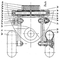
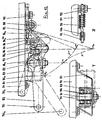
- the trailing arms 3 are each connected to the structure 4 via two auxiliary links 1, 2 , which is screwed onto the stand board 11 and in this example consists of simple angle profiles.
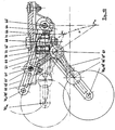
- the handlebars On the front axle, left in Fig. 1, the handlebars are shown in normal position (straight ahead); on the rear axle in a position that corresponds to extreme cornering: the inside left trailing arm 3 "' is drawn in the fully sprung position and the outside right trailing link 3"" in the fully sprung position.
- the lines of action of the two auxiliary links 1, 2 enclose an angle a and intersect at the instantaneous pole M about which the trailing link 3 is currently rotating Lines of action on the inside of the (spring-loaded) pole Me and on the outside of the (spring-loaded) pole Ma.
- the momentary poles move on pole path P.
- a part of the swivel joints must be designed as a cardan or ball joint in order to allow the longitudinal control arm to be steered by the angle ⁇ in plan view (FIG. 2).
- these are the joints 5, 7, 8, while the joint 6 remains as a swivel joint in order to be able to support the torsional forces introduced by the wheel 10 and transmitted via the trailing arm 3 .
- the lateral support would be missing.
- the constructive design of the handlebars and joints as well as their mode of action are not dealt with here; they are largely identical to the components from the second exemplary embodiment (FIGS. 3-8) and are dealt with in more detail there.
- the kinematic cross-connection 9 is designed here as a swivel joint: on the trailing arms 3 , a shaft 15 'is pressed in on the left and a pipe 15 "is pressed in on the right, which surround one another concentrically and are supported one inside the other by the sliding bushes 16' and 16" .
- these also permit a displacement movement in the axial direction, which is necessary in order to prevent the trailing arms from being squeezed when cornering.
- the steering angle ⁇ is greater, the further the connecting element 9 is in the vertical direction from the respective instantaneous pole by which the associated trailing arm rotates (and the smaller, the longer the trailing arm and the longer the transverse connection).
- the vertical distance to the instantaneous pole can be varied as desired via the angle ⁇ of the two auxiliary links to one another, in the present exemplary embodiment it is far below the standing board (even below the roadway), although all the links are arranged above. This illustrates the kinematic advantage over the parent registration.
- the cross-connection is moved in the other direction, i.e. away from the wheels, the opposite effect results, ie the wheels tilt even further towards the inside of the curve like the standing board.
- Similar kinematic variation options can be used if the auxiliary links, as in the second exemplary embodiment, are selected to be of different lengths.
- the wheel suspension also has a second degree of freedom that is used for the suspension.
- the main function of the suspension is to allow a relative movement between the body and the road (which in turn is made possible by the relative movements of the handlebars relative to the body) to cushion the bumps in the road surface and then to allow the body to move again as quickly as possible (i.e. without annoying reverberation, which is good damping assumes) to return to its normal position.
- lifting suspension it can also be used to position the vehicle straight ahead or to set it up in the horizontal starting position. (Rolling is the side slope of the body when cornering in motor vehicle construction).
- the steering reset can either take place via separate suspension elements or - as is the case in Fig. 1 - with the lifting suspension.
- four tension springs 12 are selected as spring elements, which are suspended at the top of the trailing arms and at the bottom of the stand board in the spring element holders 13, 14 and on which the stand board is "hanging". The springs are deflected with every spring-in and spring-out movement of their trailing arm and are therefore effective for both steering and suspension movements (roll and lift suspension).
- the roller board from FIG. 1 is also equipped with foot straps 17 and a so-called mast foot 18 , with which a surf sail rig 20 (of which only the lower part of the mast is shown in broken lines in FIG. 1) can be attached to the stand board. So that the rig can be inclined to control and meter the wind power on all sides, it is connected to the mast base via a universal joint 19 (usually a rubber notch bearing). Since these are commercially available standard parts, they are not described in detail here.
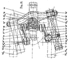
- a similar (quasi-flat) four-link chain is shown in a detailed version, but in contrast to Fig. 1, the spring forces are not via two tension springs per axis, but rather via a central compression spring (32 ) are supported on the body or standing board, and the handlebars are not arranged above, but below the standing board.
- the "first" auxiliary arm 21 (facing the wheel) is always under pressure and the "second” auxiliary arm 22 is always under tension.
- the distance between the trailing arm-side joints 25, 26 is smaller than the distance between the body-side joints 27, 28 .
- the "second" trailing arm-side joint ( 26 ) is designed as a swivel joint, while commercially available ball joints were chosen for the remaining 3 joints.
- the two joints 25, 27 of the first auxiliary link 21 are pure ball joints (the steel ball heads rotate in plastic ball sockets which are sealed by elastic sleeves and are mounted in steel housings);
- the gimbal joint 28 of the second auxiliary link is shown as an angle joint (swivel joint with a spherical sliding surface; does not allow angular deflections as large as pure ball joints).
- the angle joint 28 is screwed into the auxiliary link 22 and secured by the lock screw 39
- the rotary joint 26 is to reduce the component count, a structural unit with the storage of the connecting member 29, via the kinematic occurs the cross-laminated to the opposite trailing arms.
- the connecting element 29 is designed here as a separate tube which concentrically surrounds the tube pieces 35 ', 35 " pressed into the cast aluminum longitudinal link 23', 23" and is supported on the latter by the sliding bushes 36 .
- the tube pieces 35 ', 35 "in turn comprise the bushings 38', 38" of the swivel joints 26 via sliding bushes ( 37 ).
- the shafts 38 are pressed into the "second" auxiliary link 22 and connected to the angle joint 28 via them.
- This "double" swivel joint thus allows both a rotation of the trailing arms 23 relative to their auxiliary links 21, 22 and a rotation of the trailing arms relative to one another or to the connecting element 29.
- the bushing pairs 36, 37 are each mounted at a large distance from one another in order to achieve the greatest possible to obtain a broad support base for the forces and moments that are introduced by the wheels into the trailing arms.
- the material properties of the spring element can be changed (e.g. via the density of the Foam), there are numerous variation options for fine-tuning suspension and damping behavior.
- the connecting element 29 is in the normal position approximately vertically above the virtual rotary pole M.
- the connecting element forms a structural unit with the rotary bearing 26
- the associated auxiliary link must be used for this 22 in the normal position are approximately vertical and the other auxiliary link 21 is tilted accordingly in order to obtain a position of the instantaneous pole M exactly below the cross connection.
- the different lengths of the auxiliary links 21 and 22 have the effect that the rotary joint 26 during rebound travels a greater distance than during compression, so that it is relative to the standing surface 31 outside of the curve is in a higher position (26 ") as the inside of the curve (26 ') and thus the connecting element 29 is slightly inclined in the front view (Fig.
- the connecting element 29 has some axial play between the trailing arms 23 ' and 23 " in order to enable axial displacement of the trailing arms (in the transverse direction of the vehicle) to one another.
- the trailing arms are transverse in their transverse joints via their swivel joints 26' and 26 " and auxiliary link 22 ' or 22" are fixed to the body and therefore not only perform a rotational movement relative to each other during asynchronous deflection and extension, but also a slight displacement movement. Since the connecting tube is also rotatable relative to the trailing arms (or their pipe sections 35 ', 35 " ), it would assume an undefined position without the spring element 32 , against which it always rests and is fixed by friction.
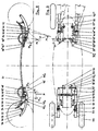
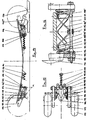
- FIG. 8 shows two exemplary embodiments of a four-bar chain, each with three rotary and one thrust joint: on the front axle, on the left in the picture, as a thrust crank drive (with the body-side joint 48 ' as a thrust joint) and on the rear axle as a crank loop (with the trailing arm-side joint 46 "' as a sliding joint).
- the thrust joint is realized on the front axle in the form of a rail 48 ' (slightly curved in the side view) in which - similar to the suspension of a sliding door - a small wheel 42' rolls, which is mounted on the longest arm 43 by means of a swivel joint 46 ' and is guided through the rail.
- the "first" auxiliary link 41 with its two ball joints 45 and 47 corresponds in principle to the auxiliary links 1 and 21 of the previous examples, while the function of the second auxiliary link as a transmission link between the thrust joint 48 'and the pivot joint 46' is taken over here by the wheel 42 '.
- a straight rail could also be used (then there would be a straight-thrust crank drive), but the curved path chosen here has the advantageous property in some applications that the instantaneous pole during compression and rebound (shown in dashed lines) is less pronounced in the vertical direction moves and thus ensures a travel behavior that is more independent of the travel. If the rail were curved in the other direction, ie downwards at its ends, the pole track would be correspondingly steeper.
- the thrust crank drive has the advantage over the four-swivel chain that the swivel 46 'moves on a (almost) horizontal path and thus takes up only minimal vertical space.
- This configuration space advantage is fully exploited in the configuration of FIG. 8:
- the auxiliary link 41 is arranged in such a way that, when fully deflected - the most critical driving condition with regard to ground clearance - it almost bears against the underside of the standing board.
- Both the ball joint of the trailing arm 45e and its swivel joint 46'e are here in their highest vertical position, that is to say the greatest possible distance from the roadway, so that an extremely low standing board position can be achieved.
- the fact that the auxiliary link moves away from the standing board when rebounding ( 45a ) is irrelevant to the ground clearance.
- the auxiliary link on the outside occupies a position (45'a) in which - like the large vertical distance of the (sprung) instantaneous pole Ma from the path of the swivel joint 46 'shows - a very strong sliding movement of the trailing arm in the horizontal direction and thus causes a large change in steering angle.
- a thrust joint in the form of a telescopic shock absorber (similar to the McPherson strut known from automotive engineering) is used, which is more complex than the front axle, but is more resistant to wear and corrosion.
- a piston rod 42 "' with attached piston 46"' slides in a hollow cylinder, which forms a structural unit with the trailing arm 43 "' and displaces a hydraulic fluid (eg shock absorber oil) from a cylinder chamber when it springs in and out
- a hydraulic fluid eg shock absorber oil
- the other displaced hydraulic fluid flows through the valves 55 in the piston and opposes the piston movement a flow resistance (due to fluid friction) which dampens the vehicle vibrations and can be varied as desired via the adjustment of the valves, for example via the opening cross section of the Valves or via the spring preload when using spring-loaded check valves.
- the piston rod 42 "'performs the function of the" second "auxiliary link, which by means of the ball joint 48 "'at the construction 44"' g is stored.
- Its trailing arm-side joint is the thrust joint, which is composed of the piston rod 42 "', the piston 46"' and the hollow cylinder.
- the first auxiliary link 43 "' with its ball joints 45"' and 47 “' and the connecting element 49"' (which is designed as a tube in FIG. 3-7, which comprises two shafts of the same diameter concentrically) are functionally identical to the corresponding ones Components of the front axle.
- the crank loop of the rear axle therefore has a kinematic behavior similar to that of the thrust crank drive of the front axle, but with a much steeper pole track; ie with an even more declining roll kinematics.
- FIG. 9 shows the wheel suspension from FIG. 8 in a top view, although some functional parts are varied compared to the side view: on the front axle, on the left in the picture, a functionally equivalent swivel joint 58 'is used instead of the wear-prone sliding joint 48'.
- a functionally equivalent swivel joint 58 ' is used instead of the wear-prone sliding joint 48'.
- the axis of the pivot joint 58 ' is approximately vertical and the associated (“second") auxiliary link 56' extends roughly across the direction of travel.
- the longitudinal link-side joint 57 'of the auxiliary link 56' therefore moves in a plan view on a circular path around the pivot joint 58 ', but describes an approximately horizontal straight line in the side view, so that there is kinematically straight-line guidance in the projection onto the plane of the drawing.
- This variant therefore combines the practical advantages of the four-link chain (no wear-prone straight guide joints) with the kinematic advantages of the thrust crank drive (low vertical space requirement). It is one of the four-link chains because the axes of rotation of the two auxiliary links (41 'and 56') are not arranged parallel to each other.
- a variant of the spatial four-link chain with a kinematic cross-connection (derived from the front axle suspension of FIG. 9) is carried out in detailed construction.
- an additional practical advantage is used, which results from the vertical axis of rotation of the "second" auxiliary link 62: the two auxiliary links are suspended here on a common pivot bearing 68 and rigidly connected to one another.
- This component is referred to below as a cross member 69, into which a shaft 74 is cast and at the ends of which the longitudinal links 63 are guided on swivel joints 66 .
- the swivel joints 66 and 68 are each designed as double-row ball bearings 76 and 78 , the outer rings of which are pressed into the trailing arms 63 and the cross member 69, and the inner rings of which are pushed onto the shaft 80 and the screw of the swivel joint 68 and through the spacer tubes 75 and 77 are separated.
- the cross member 69 rigidly connects the left trailing arm 63 ' to the right 63 " and thus also advantageously takes over the function of the kinematic cross-connection. Since it is attached directly to the body by means of the swivel joint 68, it points with the rotation around this joint.
- this degree of suspension freedom consists in the fact that the kinematic cross-connection can also move in the longitudinal direction of the vehicle relative to the bodywork, thus allowing the two trailing arms to deflect or rebound synchronously).
- the (first) auxiliary link 61 is arranged "upside down", ie the body-side ball joint 67 is located below the trailing arm side ball joint 65 , as in FIG. 1, whereby the auxiliary link 61 is always subjected to tension .
- this arrangement has the advantage that the auxiliary link does not approach its extended position when it is deflected, but when it springs out, so that - as already mentioned - the body does not lower when the side is inclined, but rather rises ("support effect" or progressive roll kinematics).
- Twist beam wheel suspension offers and on the detailed in the master registration is received.
- the rigid axle roller boards to call much better cornering power of the wheels through the inclination of the wheels with the base board is brought about in and out of curves especially beneficial when "pumping" in fast change curves (higher speeds possible).
- This could increase this curve layering effect be that the steering axis defined by the pivot 68 and thus also the path of the rotary joints 66 in the side view (Fig. 10) somewhat clockwise would be pivoted.
- the wheel suspension has - although kinematically completely different - a certain similarity to a special form of the rigid axle wheel suspension on, which is known from the published patent application 28 45 942.
- trailing arms (swing arms" 18, 20) rotatably suspended on which the wheels (26, 28) are mounted. These trailing arms are however so short that they have no significant influence on the steering and Fall behavior of the wheels.
- Their function is only to: For the purpose of cushioning road impacts, a relative movement in vertical Allow direction between the cross member and the wheels; therefore they are via additional suspension elements (30, 82, 84, 116, 118, 176) with the cross member 16 connected.
- the steering function is performed solely by the cross member according to the usual Principle of the rigid axle wheel suspensions for roller boards:
- the rigid axle or the Crossmember is over a swivel bearing (pivot 44 with hole 36) hung on the underside of the standing board and is thus at a side tilt of the standing board forced to turn; the Resetting to the straight-ahead position takes place via a spring element ("buffer" 48).
- the size of the steering lock i.e. the assignment of steering angle and side inclination of the standing board, is determined by the angular position of the swivel joint 36/44.
- the axes of rotation must be inclined so that their lines of action cut below the standing board (otherwise the steering lock would be in the wrong direction).
- both turns are made against the resistance of independent spring elements: the steering movement against the buffer 48 (roll suspension) and the spring movement against the suspension elements, e.g. 30 (lifting suspension). Since both spring elements are connected in series and can therefore spring independently of each other, the suspension functions do not separate properly, i.e. the buffer 48 can also when springing respond and the suspension element when steering and vice versa. The result is an indifferent driving behavior influenced by many coincidences (e.g. vibration processes when driving over bumps where the axle beam 16 can swing back and forth between the springs 48 and 30). In the Master registration will address these disadvantages in detail.
- Helical compression springs as in Fig. 12/13 could also be arranged in an analogous arrangement in Fig. 11/12 are used to cushion the cross member 69 there against the structure 64. Since this cross member 69, however, without a longitudinal degree of freedom is rotatably attached to the structure, such springs would only be used for rotary movements of the cross member about its vertical axis of rotation and thus only used for steering reset (roll suspension). You would be in Fig. 10/11 only makes sense if there is the kinematic weight recovery effect was not sufficiently implemented or an additional steering provision would be desirable to e.g. the wheels already in during a jump attributed to the flight phase in the straight ahead position.
- FIGS. 14 to 16 is a wheel suspension in the form of a quasi-flat four-link chain, which is designed in such a way that all of the auxiliary links are always subjected to tension and thus, like the auxiliary link 82 from FIGS. 12/13, can be designed as a rope.
- the four-link chain is therefore kinematically a hybrid form from the first two exemplary embodiments (FIGS. 1-2 and 3-7).
- auxiliary links 101 and 102 it also has a third auxiliary link 115 , which supports the second (102) laterally and thus makes the use of a swivel joint in the four-link chain unnecessary. All joints are therefore gimbal-type cable connections as with the auxiliary link from Fig. 12/13.
- auxiliary links on a vehicle axle consist of a single piece of rope. Its ends are thickened cylindrically and each is suspended in the first hinge 107 on the body side . From there, in its function as the "first" auxiliary link 101, it leads to the first articulated link 105 on the trailing link , which is designed as a fixed roller and is screwed to the trailing link 103 . From this role it is stretched to the role of the second longitudinal-link joint 106 , which is screwed together with the connecting element 109 to the longitudinal link 103; see rear view (Fig. 16). From this picture it can be seen that the groove of the rollers serves to guide the rope in the articulation points.
- a roller segment or - as an additional kinematic variation option - a spiral guide as on the trailing arm 83 in Fig. 12 could be used.
- the configuration in Fig. 14 offers Roll as guide elements, because here the wrap angle of the rope is far above 90 °).
- the fastening element 118 In order to prevent the rope from slipping on the rollers, it is clamped to the longitudinal link 103 by the fastening element 118 (only shown in FIGS. 14 and 15). By loosening this fastening element, the cable can be moved on the trailing arm and thus the length of the auxiliary links 101 and 102 can be varied in a simple manner.
- the rope now leads upwards from the second trailing arm-side joint 106 to the second body-side joint 108 ' and is fastened there on the stand board 111 with the aid of a clamp.
- This clamp is part of the superstructure 104 - a sheet metal construction which is pulled down from the second superstructure-side articulation point 108 to the first superstructure-side articulation point 106 and from there up to the front fastening screw on the stand board.
- the cable goes diagonally downwards from the second articulation point 108' to the center of the vehicle, is clamped there by means of the clamp 116 and the pipe protection sleeve 117 to the connecting element 109 and again leads obliquely upwards ( 115 " ) to the opposite articulation point 108 " .
- the two third auxiliary links 115 'and 115 support the connecting element 109 laterally in the manner of a truss and thus transmit the lateral forces introduced via the trailing arms to the body 104.
- the connecting element 109 is not designed as a (torsion-free) rotary or rotary thrust joint, but rather as a torsion-soft tube, as is known, for example, as a tube stabilizer from motor vehicle construction. To reduce the torsional stiffness, it can be partially or fully slotted.
- the tube 109 connects the two trailing arms 103 'and 103 "to one another in a flexurally stiff but torsionally soft manner and thus allows the two trailing arms to rotate with respect to one another about the tube axis if the trailing links deflect and retract differently (cornering).
- This rotating movement is caused by the torsional stiffness of the pipe opposes a spring resistance, with which the connecting element 109 takes over the function of the roll suspension or the steering reset.
- the torsion spring rate can be varied via the pipe wall thickness and the length of the slot in such a way that the entire roll suspension is applied by the pipe 109 alone Therefore, only one coil spring 112 is used here per vehicle axle, which engages in the center of the tube and therefore works exclusively as a lift spring, because it is not deflected in the same amount asynchronous spring and rebound movements (pure cornering).
- tube 109 is twisted during asynchronous compression and rebound, twist the trailing arms move relative to each other - without axial displacement.
- the pipe 109 does not allow length compensation, which is why here strictly speaking, there is no kinematically exact suspension either. This in the present case, however, does not have a negative impact on driving behavior, since when cornering (if the connecting element 109 in FIG.
- the wheel suspension according to the invention is used exclusively in four-wheel (or four-skid), two-axle and two-track vehicles which are controlled with both legs by means of sloping the base board.
- its main features in particular the wheels or runners inclined with the body when cornering - suggest that the torsion-beam axles should also be paired with known axle designs of single-track vehicles (such as motorcycles or bicycles), the wheels of which are also placed in the curve.
- advantages of single-track vehicles generally more dynamic cornering behavior
- those of the two-track vehicle including stability
- the exemplary embodiment from FIGS. 17/18 is also provided with a vehicle brake on the front axle.
- the braking torque is also transmitted to the front wheels 124 'and 124 "via a V-belt drive.
- the V-belts 126' and 126 which are attached with their front ends to the brake pedal lever 128 and are attached to the connecting element of the compound handlebar axle at the rear in normal driving a little bit down.
- the driver steps on the brake pedal lever 128, thereby tensioning both V-belts 126 'and 126 "against the pulleys 125' and 125" and thus generates a frictional force between the V-belt and the pulley or a braking torque on the front wheels.
- the brake upper Bowden cables could also be operated by hand, and instead of the V-belt pulleys, any other brake systems from the construction of bicycles, motorcycles or motor vehicles could also be used; such as disc, drum, rim or tire brakes.
- the torsion beam link 131 is used on the rear axle and combined with a single-track front axle 133 .
- the single-track axle 133 can be steered and is therefore similar to a bicycle, motorcycle or scooter front axle:
- the front wheel 134 is mounted in a fork 513 , which in turn is connected to the by means of an approximately vertical swivel 136
- Standboard 132 is connected and can be controlled by the driver using the handlebar 137 . Similar to a scooter, the driver stands on the stand board 132 and holds onto the handlebar 137.
- FIG. 20 A further application of the wheel suspension according to the invention in combination with an articulated vehicle body is shown in FIG. 20 .
- the footprint is divided into two in the manner of a so-called snakeboard, the two segments 142 ' and 142 "being articulated to one another via a connecting link 143.
- the swivel joints 144 twist the two segments towards each other in order to steer the vehicle in the desired direction of travel and to be able to move through rhythmic alternating cornering
- the unguided rigid axles do not allow the sides of the standing surfaces to tilt and the driver to one force an upright foot position, he can lie fully in the curve when using a torsion beam suspension and actively use its self-steering behavior.
- the vehicle could be set in motion by the snakeboard-typical meandering movements and then moved on like a snowboard by tilting the standing board , I agree Both curve techniques can also be varied with one another as desired.
- the additional application 196 02 447.1-15 describes a constructive possibility how such an Ackermann geometry is realized with skid vehicles lets: In contrast to the wheels, which exercise a "free" rotation when rolling, The runners only perform a limited rotation when they are moving in and out Rebound in their bearings relative to the trailing arm.
- the skid axis of rotation therefore does not have to be at least approximately transverse-horizontal, like wheel rotation axes be arranged to the direction of travel, but can take any angle.
- This additional degree of freedom of the skid suspension compared to the Wheel suspension is used advantageously for generating an additional Steering effect used, which overlaps the steering angle of the torsion beam axis.
- both handlebars turn around their respective instantaneous poles and hit thereby a steering angle; at the same time the runners turn in opposite directions Handlebar rotation back to their horizontal position and thereby generate an additional one Steering angle, provided the skid axis is not parallel to the kinematic Cross bond lie.
- the skid axes of rotation should be set at an angle so that somewhat reinforced by the additional steering effect of the inside steering angle and the outside of the curve is withdrawn somewhat, so that in accordance with the longer way, which the outside of the curve covers the inner runners, the curve radii are corrected and intersect at the curve center.
- Such boards can only be steered by rig control by moving the sail forward or backward is inclined. Because here the base board as well as the runners are inclined to There is almost no lateral acceleration possible to change the ice surface). Unless the ice is cleared after every snowfall, they are optimal Ice conditions - with a bare and flat ice surface - quite rare. Therefore recommends there is also the use of a suspension for ice surfers for universal applications, which costs a bit of height due to its travel requirements, but it does Even with bumpy or snow-covered ice for excellent driving characteristics provides.
- torsion beam axles according to the invention are used in the known Snake boards are used instead of their unguided rigid axles. Also there the typical snakeboard steering and locomotion (twisting both Legs to each other) due to the much more elegant snowboard curve technology (Body or hips with the base sloping inwards).
Description
Die Erfindung bezieht sich auf eine Radaufhängung gemäß der DE 44 26 337 C, welche die Radaufhängung eines vorzugsweise vierrädrigen Rollbretts beschreibt, das durch Gewichtsverlagerung bzw. durch Neigung der Standfläche zur kurveninneren Seite gelenkt wird. Im Gegensatz zu vorbekannten Rollbrettern (Skateboards, Strandsurfer o.ä.), die üblicherweise an Starrachsen aufgehängt sind, sieht die Stammanmeldung eine sogenannte Verbundlenker-Radaufhängung vor, die in Verbindung mit einer Federung gegenüber den Starrachs-Radaufhängungen für überlegene Fahreigenschaften sowohl auf der Straße als auch im Gelände sorgt.The invention relates to a wheel suspension according to DE 44 26 337 C, which describes the wheel suspension of a preferably four-wheeled roller board, by shifting weight or by tilting the base towards the inside of the curve Side is steered. In contrast to previously known roller boards (skateboards, Beach surfers or similar), which are usually hung on rigid axles the parent application a so-called twist beam suspension, which in Connection with a suspension opposite the rigid axle suspension for superior driving characteristics both on the road and off-road.
Die in dem genannten Patent beschriebene Verbundlenkerachse geht aus der aus dem Kraftfahrzeugbau bekannten Längslenker-Einzelradaufhängung hervor, bei der die Lenker im wesentlichen in Fahrzeug-Längsrichtung angeordnet und um eine Querachse drehbar am Fahrzeug-Aufbau gelagert sind (Drehgelenk). Die Lenker sowie die an deren Ende befestigten Räder drehen sich beim Ein- und Ausfedern auf einer Kreisbahn um diese Querachse und behalten hierbei stets ihren Augangs-Radsturzwinkel relativ zum Aufbau bei. Während der Geradeausfahrt bleibt daher auch der Sturzwinkel der Räder relativ zur Fahrbahn konstant, bei Kurvenfahrten führt jedoch bei Kraftfahrzeugen diese Eigenschaft zu dem Nachteil, daß sich der Aufbau und damit auch die Räder nach kurvenaußen neigen und die Räder dadurch mit zunehmender Querbeschleunigung (also mit zunehmend positivem Radsturz) an Seitenführungskraft verlieren. Für Rollbretter, deren Aufbau bzw. Standfläche zum Lenken nach kurveninnen geneigt wird, kehrt sich dagegen dieser Nachteil in einen Vorteil um, da sich hier die Räder - ähnlich wie bei einem Motorrad - mit nach innen neigen. Wie in der Stammanmeldung ausführlich beschrieben, sorgt dieses Sturzverhalten im Vergleich zu den Starrachs-Radaufhängungen, deren Radsturz relativ zur Fahrbahn stets konstant ist, zu einer Erhöhung der Seitenführungskräfte und somit zu verbesserten Kurvenfahreigenschaften (höhere Kurvengrenzgeschwindigkeiten) bzw. verbesserter Fahrsicherheit (größere Seitenkraftreserven).The twist beam axle described in the cited patent is based on the the trailing arm independent wheel suspension known from motor vehicle construction, in which the handlebars are arranged substantially in the vehicle longitudinal direction and around a Transverse axis are rotatably mounted on the vehicle body (swivel joint). The handlebars as well as the wheels attached to their ends turn when they compress and rebound on a circular path around this transverse axis and always keep their initial camber angle relative to the build. Therefore, during straight-ahead driving the camber angle of the wheels relative to the road is also constant when cornering However, this property leads to the disadvantage in motor vehicles that the Body and thus the wheels tilt to the outside of the curve and the wheels thereby with increasing lateral acceleration (i.e. with increasingly positive camber) Lose cornering power. For roller boards, their construction or standing space for Steering towards the inside of the bend turns this disadvantage into one Advantage um, because here the wheels - similar to a motorcycle - with the inside tend. As described in detail in the parent registration, this fall behavior ensures compared to the rigid axle suspension, whose camber is relative to the road is always constant, to an increase in cornering forces and thus to improved cornering characteristics (higher cornering speeds) or improved driving safety (larger side power reserves).
Eine reine Längslenker-Einzelradaufhängung ist allerdings für Rollbretter ungeeignet, da die Lenker beim Ein- und Ausfedem nicht nur ihren Sturz- sondern auch ihren Lenkwinkel relativ zum Aufbau konstant beibehalten. Damit zur Einleitung einer Kurvenfahrt die Seitenneigung des Aufbaus bzw. der Standfläche automatisch in einen Lenkwinkel umgesetzt wird, ist zwischen den gegenüberliegenden Längstenkem einer Achse ein kinematischer Querverbund erforderlich, der einen Lenkwinkel erzeugt, sobald die Lenker gegensinnig zueinander ein- und ausfedern (Indiz für Kurvenfahrt). In der Stammanmeldung sind hierzu die Längslenker in der Nähe ihres Drehgelenks jeweils mit einem Hebelarm versehen, der in etwa senkrecht zur Längsachse des Lenkers steht und an seinem Ende ein Verbindungselement zum jeweils gegenüberliegenden Lenker trägt. Beim synchronen (gleichsinnigen) Einund Ausfedern der Längslenker, wie es beim Überfahren von Bodenwellen auftritt, werden die Hebelarme und die Verbindungselemente auf beiden Fahrzeugseiten um denselben Betrag nach vorne oder hinten bewegt, wodurch die Lenker in Geradeausstellung verbleiben. Bei Kurvenfahrten dagegen, wenn die Lenker asynchron (gegensinnig) ein- und ausfedern, werden die Hebel auf der einen Seite in Fahrtrichtung und auf der anderen Seite entgegen der Fahrtrichtung ausgelenkt, wodurch - in der Draufsicht auf das Fahrzeug - jeder Lenker durch das Verbindungselement des gegenüberliegenden Lenkers um einen bestimmten Lenkwinkel verdreht wird, der in etwa proportional zur Federwegdifferenz der beiden Längslenker ist. Um den Längslenkern einen solchen Lenkeinschlag zu ermöglichen, müssen die Drehgelenke durch Kardan- oder Kugelgelenke ersetzt werden. Diese Gelenke weisen im Gegensatz zum Drehgelenk mehrere Rotationsfreiheitsgrade auf und räumen damit auch den Längslenkern - neben der Drehbewegung um die Querachse - relativ zum Aufbau einen zweiten Rotationsfreiheitsgrad ein: Die Drehung um eine in etwa vertikale Drehachse (Lenkachse). Durch den kinematischen Querverbund wird dieser zweite Freiheitsgrad jedoch wieder aufgehoben, d.h. der Lenkeinschlag der Räder steht in einer festen Zuordnung zum Neigungswinkel des Aufbaus bzw. der Standfläche.A purely trailing arm independent wheel suspension is unsuitable for roller boards, because the handlebars not only their camber but also their Maintain a constant steering angle relative to the body. In order to initiate a Cornering the side inclination of the body or the stand area automatically in a steering angle is implemented is between the opposite Längenstenkem an axis requires a kinematic cross-link, the steering angle generated as soon as the handlebars rebound and rebound in opposite directions (indication for Cornering). In the master registration, the trailing arms are close to yours Swivel joint each provided with a lever arm that is approximately perpendicular to Longitudinal axis of the handlebar is and at its end a connecting element to each opposite handlebar carries. With synchronous (in the same direction) single and Rebound of the trailing arms, as occurs when driving over bumps, the lever arms and the connecting elements on both sides of the vehicle moves the same amount forward or backward, causing the handlebars to be in the straight ahead position remain. On the other hand, when cornering, when the handlebars are asynchronous Coming in and out (in opposite directions), the levers are on one side in the direction of travel and deflected on the other side against the direction of travel, whereby - In the top view of the vehicle - each handlebar through the connecting element the opposite handlebar is rotated by a certain steering angle, which is roughly proportional to the travel difference of the two trailing arms. To the The swivel joints must enable trailing arms such a steering angle be replaced by cardan or ball joints. These joints point in contrast to the swivel joint several degrees of freedom of rotation and thus clear also the trailing arms - in addition to the rotational movement about the transverse axis - relative to the Establish a second degree of freedom of rotation: The rotation about an approximately vertical Axis of rotation (steering axis). This is due to the kinematic cross-connection second degree of freedom, however, canceled again, i.e. the steering angle of the wheels stands in a fixed assignment to the angle of inclination of the body or the footprint.
Diese Zuordnung wird im wesentlichen von der Position der Verbindungselemente bestimmt. Von Bedeutung sind hier insbesondere die Hebellänge (der vertikale Abstand zwischen den Verbindungselementen und der kardanischen Anlenkung der Längslenker am Aufbau) die Länge des Querverbunds (der horizontale Abstand der beiden gegenüberliegenden Hebelarme voneinander) sowie die Lenkerlänge (Abstand der Räder von der kardanischen Anlenkung): Je länger die Hebelarme im Verhältnis zur Lenkerlänge einerseits sowie zur Länge des Querverbunds andererseits ausgeführt sind, desto größer wird der Lenkeinschlag. Da sich die Hebelarme vornehmlich in vertikaler Richtung erstrecken, führt dies insbesondere bei kleinen und wendigen Rollbrettern (z.B. Skateboards), mit denen sehr enge Kurvenradien gefahren werden sollen, zu dem Nachteil einer relativ großen vertikalen Bauhöhe, die keine besonders niedrige Standposition zuläßt.This assignment is essentially based on the position of the connecting elements certainly. The length of the lever (the vertical distance) is of particular importance here between the connecting elements and the cardanic linkage of the Trailing arm on the body) the length of the cross composite (the horizontal distance of the two opposite lever arms from each other) and the handlebar length (Distance of the wheels from the cardanic linkage): The longer the lever arms in the Relationship to the length of the handlebar on the one hand and the length of the cross-connection on the other are executed, the greater the steering angle. Because the lever arms extend primarily in the vertical direction, this leads especially to small ones and agile roller boards (e.g. skateboards) with which very tight curve radii to be driven, to the disadvantage of a relatively large vertical height, which does not allow a particularly low standing position.
Hauptaufgabe der vorliegenden Erfindung ist es daher, für sehr wendige Rollbretter die Radaufhängung unter Beibehaltung der wesentlichen kinematischen Eigenschaften derart weiter zu verbessern, daß sie eine niedrigere Bauhöhe des Rollbretts und eine extrem niedrige Standposition erlaubt. The main object of the present invention is therefore for very agile roller boards the wheel suspension while maintaining the essential kinematic properties further improve such that they have a lower height of the roller board and allows an extremely low standing position.
Dieses Ziel wird dadurch erreicht, daß die i.a. vertikalen Hebel aus der DE 44 26 337 C (dort z.B. 15, 35, 55), die jeweils starr an ihren Längslenkern befestigt oder in diesen inte-griert sind und die meist die Bauhöhe der einzelnen Ausführungsbeispiele bestimmen, durch je 2 Hilfslenker ersetzt werden. Die Längslenker sind dadurch nicht mehr direkt, sondern über diese Hilfslenker mit dem Aufbau bzw. der Standfläche verbunden. (Als Aufbau werden im folgenden diejenigen Trägerteile bezeichnet, die das Standbrett tragen und an denen die Hilfslenker gelagert sind). In der Seitenansicht drehen sich die Längslenker deshalb nicht mehr um einen körperfesten Drehpol - in der Stammanmeldung das kardanisch bewegliche Gelenk, z.B. 6, 46, 66 - relativ zum Aufbau, sondern jeweils um einen virtuellen Drehpol, den sogenannten Momentanpol, dessen momentane Lage im Raum von der Anordnung der Hilfslenker oder -gelenke bestimmt wird. (Der Momentanpol bewegt sich auf der sog. Polbahn; er ändert seine Lage deswegen, weil sich beim Ein- und Ausfedern neben den Längslenkern auch die Hilfslenker bewegen). Der Vorteil dieser Konstruktion gegenüber der Stammanmeldung besteht darin, daß der Momentanpol als virtueller Drehpol ohne Rücksicht auf die realen Bauteile beliebig tief oder hoch im Raum angeordnet werden kann, so daß sich auch bei eingeschränkter Bauhöhe sehr enge Kurvenradien realisieren lassen. In den folgen-den Ausführungsbeispielen wird dieser Effekt näher erläutert.This goal is achieved by the fact that the i.a. vertical lever from DE 44 26 337 C (there e.g. 15, 35, 55), each rigidly attached to their trailing arms or in these are integrated and mostly the overall height of the individual exemplary embodiments determine to be replaced by 2 auxiliary links each. The trailing arms are thereby no longer directly, but via these auxiliary links with the body or the Stand area connected. (In the following, those carrier parts are used as a structure designated, who carry the stand board and on which the auxiliary links are mounted). In the side view, the trailing arms no longer turn around a body-fixed Drehpol - in the master registration the gimbal joint, e.g. 6, 46, 66 - relative to the structure, but each around a virtual pivot, the so-called instantaneous pole, its current position in space from the arrangement the auxiliary link or joint is determined. (The current pole moves on the so-called Polbahn; it changes its position because it compresses and rebounds move the auxiliary links in addition to the trailing links). The advantage of this construction compared to the parent application is that the current pole as virtual pivot point regardless of the real components at any depth or high in the Space can be arranged so that even with limited height allow very tight curve radii to be achieved. In the following exemplary embodiments this effect is explained in more detail.
In der ebenen Getriebelehre wird eine solche Anordnung der Gelenke als Viergelenkkette bezeichnet, da die Anbindung der Längslenker an den Aufbau über 4 Gelenke erfolgt, die entweder Dreh- oder Schubgelenke oder eine Kombination aus beiden sein können:
- 4 Drehgelenke
Eine solche Viergelenkkette liegt vor, wenn der Längslenker über 2 Hilfslenker
mit dem Aufbau verbunden ist, von denen jeder mittels eines Drehgelenks einerseits
am Aufbau und andererseits am Längslenker befestigt ist. Beim Einund
Ausfedern drehen sich jeweils die Hilfslenker um den Aufbau, der Längslenker
dagegen um den Momentanpol, der sich als Schnittpunkt der Hilfslenker-Wirkungslinien
ergibt. Siehe
Ausführungsbeispiele 1 und 2 (Fig. 1-7). - 3 Drehgelenke und 1 Schubgelenk
Wird ein aufbauseitiges Drehgelenk durch eine Geradführung (Translation
statt Rotation) ersetzt, liegt ein sog. Geradschubkurbeltrieb (z.B. Pleuel und
Kolben) vor; wird dagegen ein längslenkerseitiges Drehgelenk durch ein
Schubgelenk ersetzt, resultiert hieraus eine sog. Kurbelschleife. In beiden
Fällen ergibt sich der Momentanpol als Schnittpunkt der Wirkungslinie des
verbliebenen Hilfslenkers mit der Senkrechten auf die Geradführung. Siehe
Ausführungsbeispiele 3 und 4 (Fig. 8). - 2 Drehgelenke und 2 Schubgelenke Je nachdem, welches der übrigen Drehgelenke durch ein Schubgelenk ersetzt wird, erhält man 4 weitere Gelenkkettenvarianten (u.a. doppelte Kurbelschleife), auf die an dieser Stelle nicht näher eingegangen wird.
- 4 swivel joints Such a four-link chain is present when the trailing arm is connected to the body via 2 auxiliary links, each of which is attached to the body and to the trailing arm on the one hand by means of a swivel joint. When deflecting and rebounding, the auxiliary link rotates around the body, the trailing link on the other hand around the instantaneous pole, which results as the intersection of the auxiliary link action lines. See
embodiments 1 and 2 (Fig. 1-7). - 3 swivel joints and 1 thrust joint If a body-side swivel joint is replaced by a straight guide (translation instead of rotation), a so-called straight thrust crank drive (eg connecting rod and piston) is available; if, on the other hand, a trailing arm-side swivel joint is replaced by a thrust joint, this results in a so-called crank loop. In both cases, the instantaneous pole is the intersection of the line of action of the remaining auxiliary link with the perpendicular to the straight line. See
embodiments 3 and 4 (Fig. 8). - 2 swivel joints and 2 thrust joints Depending on which of the other swivel joints is replaced by a thrust joint, you get 4 further joint chain variants (including a double crank loop), which are not discussed in more detail here.
Dieser kurze Überblick zeigt bereits verschiedene Ausführungsmöglichkeiten der Viergelenkkette, aus denen durch geschickte kinematische Abwandlungen zahlreiche Variationen für die unterschiedlichsten Verwendungszwecke erzeugt werden können. Die Viergelenkkette erlaubt also eine wesentlich größere geometrische Flexibilität als die Radaufhängung der Stammanmeldung, bringt wegen der höheren Anzahl an Gelenken zunächst allerdings den Nachteil eines höheren Bauteileaufwands mit sich. Wie einige der nachfolgenden Ausfüh-rungsbeispiele zeigen, läßt sich dieser Aufwand jedoch u.a. durch Doppelverwendung von Gelenken oder durch Weglassen von Funktionen (z.B. Verzicht auf die Federung dort, wo sie nicht benötigt wird oder stören würde) erheblich reduzieren.This brief overview already shows different execution options of the Four-link chain, from which numerous skilful kinematic modifications Variations can be created for the most diverse purposes can. The four-link chain therefore allows much greater geometric flexibility than the wheel suspension of the parent registration, brings because of the higher However, the number of joints initially has the disadvantage of a higher component expenditure with himself. As some of the examples below show however, this effort by double use of joints or by Omission of functions (e.g. waiving the suspension where it is not required will or would interfere) significantly.
Zum besseren Verständnis wurde hier die Viergelenkkette in ihrer ebenen Ausführungsform erläutert; für die Anwendung als Radaufhängung für lenkbare Fahrzeuge können jedoch aus folgendem Grund nur räumliche Viergelenkketten eingesetzt werden: Um Lenkbewegungen zu ermöglichen, müssen sich die Längslenker in der Draufsicht nach links und rechts aus der Ebene herausdrehen können, während der Aufbau in der ursprünglichen Ebene verbleibt. Wie auch in der Stammanmeldung benötigen die Längslenker einen zusätzlichen Freiheitsgrad für die Lenkung. Da reine Drehgelenke (mit nur einem Rotationsfreiheitsgrad) und reine Schubgelenke (mit nur einem Translationsfreiheitsgrad) dies jedoch nicht zulassen würden, müssen in jeder Kette mindestens 2, maximal 3 der Drehgelenke durch Kardangelenke (2 Rotationsfreiheitsgrade) oder Kugelgelenke (3 Rotationsfreiheitsgrade) ersetzt werden; ähnliches gilt für die Schubgelenke. Mindestens eines der Gelenke muß als Drehgelenk verbleiben, da sonst die Radaufhängung relativ zum Aufbau einen Freiheitsgrad zu viel aufweisen würde und z.B. bei Einwirkung von Seitenkräften seitlich wegklappen könnte. Die "kardanisch bewegliche" Aufhängung der Längslenker, die gemäß dem Hauptanspruch ein kennzeichnendes Merkmal der vorliegenden Erfindung wie auch der Stammanmeldung ist, bedeutet also, daß sich die Längslenker im wesentlichen um eine in etwa querhorizontale Achse (zum Ein- und Ausfedern) und um eine in etwa vertikale Achse (zum Lenken), aber nicht um ihre eigene (in etwa längshorizontale) Achse drehen.For a better understanding here the four-link chain in its flat embodiment explains; for use as wheel suspension for steerable vehicles can only use spatial four-link chains for the following reason to enable steering movements, the trailing arms must be in the Can turn top view left and right out of the plane during the Structure in the original level remains. As in the parent registration the trailing arms require an additional degree of freedom for the steering. There pure swivel joints (with only one degree of freedom of rotation) and pure thrust joints (with only one degree of translation freedom) would not have to allow this in each chain at least 2, maximum 3 of the swivel joints by universal joints (2 degrees of freedom of rotation) or ball joints (3 degrees of freedom of rotation) replaced become; the same applies to the sliding joints. At least one of the joints must be as The hinge remains, otherwise the wheel suspension has a degree of freedom relative to the body would have too much and e.g. when exposed to lateral forces could fold away. The "gimbal" suspension of the trailing arms, the according to the main claim a characteristic feature of the present invention as is the parent application, means that the trailing arm in essentially around an approximately horizontal axis (for compression and rebound) and about an approximately vertical axis (for steering), but not about its own (approximately turn the longitudinal axis).
Als Alternative zu solchen Drehgelenken kann der überflüssige Freiheitsgrad allerdings auch durch einen dritten kugelgelenkgelagerten Hilfslenker aufgehoben werden, der die Radaufhängung seitlich abstützt und die Seitenkräfte auf den Aufbau überträgt (z.B. Fig. 14-16). Damit erhöht sich zwar der konstruktive Aufwand, nicht notwendigerweise aber auch die Kosten, da Kugelgelenke i.a. kostengünstiger als reine Dreh- oder Schubgelenke sind. Sie werden in hohen Stückzahlen gefertigt und stehen in den unterschiedlichsten Ausführungen als Standardteile zur Verfügung, z.B. als Kugelgelenk oder Winkelgelenk, bei denen eine Kugel in einer Kugelpfanne gleitet (meist dauergeschmiert und mit Manschetten abgedicht), oder als Elastomergelenke, wo die zu verbindenden Teile in einem elastomeren Werkstoffe gelagert sind und sich durch Verformung dieses Werkstoffes relativ zueinander bewegen können. In den nachfolgenden Ausführungsbeispielen werden i.a. Kugelgelenke eingesetzt, doch könnten stattdessen stets auch andere kardanische Gelenke verwendet, ohne die Funktion zu beeinträchtigen. Bei Verwendung von Elastomergelenken ist allerdings zu beachten, daß bei zu weichem Werkstoff die Führung der Räder nicht mehr exakt ist und bei zu hartem Werkstoff der Bewegung ein hoher Widerstand entgegengesetzt wird. The redundant degree of freedom can, however, be an alternative to such swivel joints can also be lifted by a third ball-jointed auxiliary link, which supports the wheel suspension laterally and the lateral forces on the body transmits (e.g. Fig. 14-16). This increases the design effort, but not but necessarily also the costs, since ball joints generally cheaper than are pure swivel or sliding joints. They are manufactured in large numbers and are available in various designs as standard parts, e.g. as a ball joint or angled joint, where a ball is in a ball socket slides (usually permanently lubricated and sealed with cuffs), or as elastomer joints, where the parts to be connected are stored in an elastomeric material are and move relative to each other by deformation of this material can. In the following examples, i.a. ball joints used, but other gimbal joints could always be used instead, without affecting the function. When using elastomer joints However, it should be noted that if the material is too soft, the guide of the Wheels is no longer exact and if the material of the movement is too hard a high one Resistance is opposed.
Im folgenden werden solche Viergelenkketten, die aus der ebenen Viergelenkkette abgeleitet sind und bei denen zumindest in der Geradeausfahrt die Lenker sich um querhorizontale Drehachsen bewegen, als "quasi-ebene" Viergelenkketten bezeichnet, um sie von den "echten" räumlichen Viergelenkketten zu unterscheiden, bei denen sich die Hilfslenker z.T. um vertikale oder schräge Achsen drehen.In the following, such four-link chains are made from the flat four-link chain are derived and in which the handlebars at least when driving straight ahead move transverse horizontal axes of rotation, referred to as "quasi-flat" four-link chains, to differentiate them from the "real" spatial four-link chains, at which the auxiliary handlebars partly rotate around vertical or oblique axes.
Die wichtigsten kinematischen Merkmale der Erfindung gegenüber dem Stand der Technik lassen sich wie folgt zusammenfassen:
- Die beiden Räder einer Achse sind nicht an einem gemeinsamen Achskörper (z.B. Starrachse), sondern einzeln an separaten Radträgem, den Längslenkem, aufgehängt.
- Die Längslenker einer Achse sind durch einen kinematischen Querverbund derart miteinander gekoppelt, daß sie bzw. die Räder bei synchronen Ein- und Ausfederbewegungen ihren Lenk- und Sturzwinkel relativ zum Aufbau konstant beibehalten, bei asynchronen Ein- und Ausfederbewegungen dagegen einen Lenkwinkel zur kurveninneren Seite einschlagen, ohne dabei ihren Sturzwinkel relativ zum Aufbau zu verändern.
- Die Längslenker sind nicht direkt, sondern jeweils über
mindestens 2 Hilfslenker gelenkig mit dem Aufbau verbunden und drehen sich daher nicht um einen festen, sondern um einen virtuellen Drehpol (Momentanpol) relativ zum Aufbau. - Aus dieser Konstellation resultiert ein zweites Merkmal: Da die
Hilfslenker über je 2 Gelenke verfügen, ist jederLängslenker über mindestens 4 Gelenke mit dem Aufbau verbunden (daher auch die Bezeichnung "Viergelenkkette"),wobei sich 2 dieser Gelenke am Längslenker und die übrigen beiden am Aufbau bzw. Standbrett befinden.
- The two wheels of an axle are not suspended on a common axle body (eg rigid axle), but individually on separate wheel supports, the trailing arms.
- The trailing arms of an axle are coupled to one another by a kinematic cross-connection in such a way that they or the wheels keep their steering and camber angles constant relative to the body during synchronized spring-in and rebound movements, while a steering angle on the inside of the curve turns in asynchronous spring-in and spring-out movements. without changing their camber angle relative to the body.
- The trailing arms are not directly connected to the body, but are each articulated via at least two auxiliary links and therefore do not rotate about a fixed, but a virtual pivot (instantaneous pole) relative to the body.
- This constellation results in a second characteristic: Since the auxiliary links each have 2 joints, each trailing link is connected to the body via at least 4 joints (hence the name "four-link chain"), with 2 of these joints on the trailing link and the other two on Structure or stand board.
Die vielseitigen kinematischen und konstruktiven Eigenschaften der Viergelenkkette lassen sich nicht nur zur Bauraumoptimierung nutzen, sie werden im folgenden u.a. auch für die Optimierung des Fahrverhaltens herangezogen. Durch geschickte Anordnung der Gelenke kann beispielsweise erreicht werden, daß sich der Aufbau bei Einleiten einer Kurvenfahrt anhebt und am Ausgang der Kurve wieder absenkt, so das das Standbrett ausschließlich durch das Gewicht des Fahrers wieder in seine horizontale Geradeausstellung zurückgestellt werden kann (sog. Gewichtsrückstellung; üblicherweise erfolgt bei Rollbrettern die Lenkungsrückstel-lung durch spezielle Federelemente). Bei der Beschreibung von Fig. 9 und 10 wird dieser äußerst vorteilhafte Effekt näher erläutert.The versatile kinematic and constructive properties of the four-link chain can not only be used to optimize installation space, they are also used to optimize driving behavior. By clever arrangement the joints can be achieved, for example, that the structure at Initiation of cornering raises and lowers again at the exit of the curve, see above that the standboard is returned to it solely by the weight of the driver horizontal straight position can be reset (so-called weight reset; In the case of roller boards, the steering reset is usually carried out by special Spring elements). 9 and 10, this becomes extreme advantageous effect explained in more detail.
Ein zusätzliches Ziel der Erfindung ist die Übertragung der herausragenden Fahreigenschaften der erfindungsgemäßen Radaufhängung auch auf Kufenfahrzeuge, wie sie z.B als Eissurfer Verwendung finden. In der Zusatzanmeldung 196 02 447.1-15 zum DE-Patent 44 26 337 wird vorgeschlagen, die kinematischen Vorteile der Verbundlenkerachsen auch bei derartigen Kufenfahrzeugen zu nutzen. Im Rahmen der vorliegenden Erfindung soll darüber-hinaus der wahlweise Einsatz von Kufen auch bei Verbundlenkerachsen auf Basis von Viergelenkketten mit einbezogen werden.An additional aim of the invention is the transfer of the outstanding driving characteristics the wheel suspension according to the invention also on skid vehicles, such as they are used e.g. as ice surfers. In additional application 196 02 447.1-15 DE Patent 44 26 337 proposes the kinematic advantages of the torsion beam axles can also be used with such skid vehicles. As part of the In addition, the present invention is also intended for the optional use of skids for torsion beam axles based on four-link chains.
Es zeigen:
- Fig. 1
- Schematische Darstellung eines Rollbretts mit einer Radaufhängung auf Basis einer quasi-ebenen Viergelenkkette in der Seitenansicht.
- Fig. 2:
- Draufsicht von Fig.1.
- Fig. 3:
- Seitenansicht einer bevorzugten und konstruktiv detailliert ausgeführten Radaufhängung ebenfalls auf Basis einer quasi-ebenen Viergelenkkette bei Geradeausfahrt.
- Fig. 4:
- Draufsicht von Fig 3.
- Fig. 5:
- Seitenansicht der Radaufhängung aus Fig. 3 bei Kurvenfahrt.
- Fig. 6:
- Draufsicht von Fig 5.
- Fig. 7:
- Vorderansicht von Fig 5
und 6. - Fig. 8:
- Schematische Darstellung eines Rollbretts mit zwei Varianten von Radaufhängungen auf Basis von quasi-ebenen Viergelenkketten mit jeweils einem Schubgelenk; in der Seitenansicht.
- Fig. 9:
- Draufsicht auf das Rollbrett von Fig. 8, das hier allerdings an Vorder- und Hinterachse gegenüber Fig. 8 funktionsähnliche, jedoch kinematisch unterschiedliche Radaufhängungen jeweils auf Basis einer räumlichen Viergelenkkette aufweist.
- Fig. 10:
- Seitenansicht einer bevorzugten und konstruktiv detailliert ausgeführten Radaufhängung auf Basis einer räumlichenViergelenkkette bei Kurvenfahrt.
- Fig. 11:
- Draufsicht von Fig 10.
- Fig. 12:
- Seitenansicht einer weiteren Variante einer Radaufhängung auf Basis einer räumlichenViergelenkkette bei Geradeausfahrt.
- Fig. 13:
- Draufsicht von Fig 12.
- Fig. 14:
- Seitenansicht eines Rollbretts mit einer Rad- oder Kufenaufhängung auf
Basis einer quasi-ebenen
Viergelenkkette mit jeweils 3 Hilfslenkern. - Fig. 15:
- Draufsicht von Fig 14.
- Fig. 16:
- Ansicht von hinten der Vorderachs- Radaufhängung aus Fig. 14/15 in vergrößertern Maßstab.
- Fig. 17:
- Seitenansicht eines Fahrzeugs mit einer beliebigen erfindungsgemäßen Verbundlenker-Radaufhängung an der Vorderachse und einer einspurigen Hinterachse.
- Fig. 18:
- Draufsicht von Fig 17.
- Fig. 19:
- Draufsicht eines Fahrzeugs mit einer beliebigen erfindungsgemäßen Verbundlenker-Radaufhängung an der Hinterachse und einer einspurigen Vorderachse.
- Fig. 20:
- Draufsicht eines Fahrzeugs mit zwei beliebigen erfindungsgemäßen Verbundlenker-Radaufhängungenan in Kombination mit einer zweigeteilten Standfläche.
- Fig. 1
- Schematic representation of a roller board with a wheel suspension based on a quasi-flat four-link chain in a side view.
- Fig. 2:
- Top view of Fig.1.
- Fig. 3:
- Side view of a preferred and constructively detailed wheel suspension also based on a quasi-flat four-link chain when driving straight ahead.
- Fig. 4:
- Top view of Fig. 3rd
- Fig. 5:
- Side view of the wheel suspension from Fig. 3 when cornering.
- Fig. 6:
- Top view of FIG. 5.
- Fig. 7:
- 5 and 6.
- Fig. 8:
- Schematic representation of a roller board with two variants of wheel suspensions based on quasi-flat four-link chains, each with a sliding joint; in the side view.
- Fig. 9:
- Top view of the roller board of FIG. 8, which here has functionally similar but kinematically different wheel suspensions on the front and rear axles compared to FIG. 8, each based on a spatial four-link chain.
- Fig. 10:
- Side view of a preferred and constructively detailed suspension based on a spatial four-link chain when cornering.
- Fig. 11:
- Top view of Fig. 10
- Fig. 12:
- Side view of another variant of a wheel suspension based on a spatial four-link chain when driving straight ahead.
- Fig. 13:
- Top view of Fig. 12
- Fig. 14:
- Side view of a roller board with a wheel or skid suspension on the basis of a quasi-flat four-link chain, each with 3 auxiliary links.
- Fig. 15:
- Top view of Fig. 14.
- Fig. 16:
- Rear view of the front axle wheel suspension from Fig. 14/15 on an enlarged scale.
- Fig. 17:
- Side view of a vehicle with any torsion beam suspension according to the invention on the front axle and a single-track rear axle.
- Fig. 18:
- Top view of Fig. 17.
- Fig. 19:
- Top view of a vehicle with any torsion beam suspension according to the invention on the rear axle and a single-track front axle.
- Fig. 20:
- Top view of a vehicle with any two torsion beam suspension according to the invention in combination with a two-part footprint.
Im ersten Ausführungsbeispiel (Figur 1 und 2) ist die Ausgangsform der Viergelenkkette
(mit vier Dreh- bzw. Kardan- oder Kugelgelenken) realisiert. Hierbei sind die
Längslenker 3, wie aus der Seitenansicht (Fig. 1) ersichtlich, über jeweils 2 Hilfslenker
1, 2 mit dem Aufbau 4 verbunden, der auf das Standbrett 11 aufgeschraubt ist
und in diesem Beispiel aus einfachen Winkelprofilen besteht. An der Vorderachse,
links in Fig. 1, sind die Lenker in Normallage (Geradeausfahrt) dargestellt; an der
Hinterachse jeweils in einer Position, wie sie einer extremen Kurvenfahrt entspricht:
Der kurveninnere, linke Längslenker 3"' ist in voll eingefederter und der kurvenäußere,
rechte Längslenker 3"" in voll ausgefederter Position gezeichnet. Da der Abstand
zwischen den längslenkerseitigen Drehgelenken 5,6 größer ist als der Abstand
zwischen den aufbauseitigen Drehgelenken 7, 8, schließen die Wirkungslinien
der beiden Hilfslenker 1, 2 einen Winkel a ein und schneiden sich im Momentanpol
M, um den sich der Längslenker 3 momentan dreht. An der Hinterachse schneiden
sich die Wirkungslinien kurveninnen im (eingefederten) Momentanpol Me und kurvenaußen
im (ausgefederten) Pol Ma. Während des Ein- und Ausfedervorgangs
bewegen sich die Momentanpole auf der Polbahn P.In the first exemplary embodiment ( FIGS. 1 and 2 ), the initial shape of the four-bar chain (with four swivel or cardan or ball joints) is realized. Here, the trailing
Wie oben erwähnt, muß ein Teil der Drehgelenke als Kardan- oder Kugelgelenk
ausgeführt werden, um in der Draufsicht (Fig. 2) eine Lenkbewegung der Längslenker
um den Winkel λ zu ermöglichen. Im vorliegenden Beispiel sind dies die Gelenke
5, 7, 8, während das Gelenk 6 als Drehgelenk verbleibt, um die vom Rad 10 eingeleiteten
und über den Längslenker 3 übertragenen Torsionskräfte abstützen zu können.
(Ohne ein solches Drehgelenk in der Viergelenkkette würde die seitlich Abstützung
fehlen). Auf die konstruktive Ausführung der Lenker und Gelenke sowie auf
ihre Wirkungsweise wird hier nicht näher eingegangen; sie sind größtenteils identisch
mit den Bauteilen aus dem zweiten Ausführungsbeispiel (Fig. 3-8) und werden
dort ausführlicher behandelt.As mentioned above, a part of the swivel joints must be designed as a cardan or ball joint in order to allow the longitudinal control arm to be steered by the angle λ in plan view (FIG. 2). In the present example, these are the
Der kinematische Querverbund 9 ist hier als Drehgelenk ausgeführt: An den Längslenkern
3 sind links eine Welle 15' und rechts ein Rohr 15" eingepreßt, die sich konzentrisch
umfassen und durch die Gleitbuchsen 16' und 16" ineinander gelagert
sind. Diese lassen neben der Drehbewegung auch ein Verschiebebewegung in
axialer Richtung zu, die erforderlich ist, um bei Kurvenfahrt ein Verzwängung der
Längslenker zu vermeiden. Bei Geradeausfahrt bzw. bei allen Fahrzuständen, in
denen die beiden Längslenker einer Achse synchron ein- oder ausfedern, verdrehen
sich die Längslenker nicht relativ zueinander und die Verbindungselemente verbleiben
stets quer zur Fahrtrichtung, siehe Vorderachse. Bei asynchronen Ein- und
Ausfederbewegungen - wie an der Hinterachse dargestellt - führen die Längslenker
eine Relativbewegung zueinander aus und drehen sich gleichzeitig um ihren jeweiligen
Momentanpol relativ zum Aufbau. Da infolge dieser Drehbewegung der linke
hintere Längslenker 3''' nach vorne und der rechte 3'''' nach hinten verschoben
wird, verdrehen sich in der Draufsicht beide Längslenker (da sie über den Querverbund
9 biegesteif miteinander gekoppelt sind) um den Lenkwinkel λ und lenken das
Rollbrett in die Kurve.The
Der Lenkwinkel λ ist umso größer, je weiter die Verbindungselement 9 in vertikaler
Richtung vom jeweiligen Momentanpol entfernt sind, um den sich der zugehörige
Längslenker dreht (und umso geringer, je länger die Längslenker sind und je länger
der Querverbund ist). Der vertikale Abstand zum Momentanpol läßt sich über den
Winkel α der beiden Hilfslenker zueinander beliebig variieren, in vorliegendem Ausführungsbeispiel
liegt er weit unterhalb des Standbretts (sogar unter der Fahrbahn),
obwohl alle Lenker oberhalb angeordnet sind. Dies verdeutlicht den kinematisch
Vorteil gegenüber der Stammanmeldung.The steering angle λ is greater, the further the connecting
Falls sich der Querverbund, wie in Fig. 1 links in der Ausgangslage realisiert, in vertikaler
Richtung genau über dem Momentanpol befindet, bleiben die Verbindungselemente
9 zweier benachbarter Längslenker beim Ein- und Ausfedern stets in gleicher
Höhe und der Querver-bund verbleibt - auch beim Lenken - in horizontaler Lage.
Damit behalten die Räder auch ihren Sturzwinkel relativ zum Aufbau bzw. zur
Standfläche bei. Würde der Querverbund jedoch bei unveränderter Position des
Momentanpols weiter vorne oder hinten positioniert werden (z.B. an der Hinterachse
nach hinten in Richtung der Räder), macht er beim asynchronen Ein- und Ausfedern
die gegenläufige Höhenänderungen der Längslenker mit (die umso stärker ausfallen,
je näher der Querverbund zu den Rädern rückt) und wandert somit aus seiner
horizontalen Lage aus; d.h. in der Vorder- oder Rückansicht werden die Längslenker
und damit auch die Räder entsprechend aus ihrer quer-horizontalen Position herausgedreht
und ändern ihren Sturzwinkel relativ zum Aufbau. Je weiter der Querverbund
in Richtung der Räder verschoben wird, desto mehr verliert sich dabei der
"Kurvenleger-Effekt" (die Räder neigen sich also nicht mehr so stark wie das Standbrett
in die Kurve). Im Extremfall, wenn sich der Querverbund genau zwischen den
Rädern befindet, bleibt der Sturz relativ zur Fahrbahn konstant wie bei der Starrachse.
Wird der Querverbund dagegen in die andere Richtung verlegt, also von den
Rädern weg, ergibt sich der gegenteilige Effekt, d.h. die Räder neigen sich noch
weiter nach kurveninnen wie das Standbrett. Ähnliche kinematische Variationsmöglichkeiten
lassen sich anwenden, wenn die Hilfslenker, wie im zweiten Ausführungsbeispiel,
unterschiedlich lang gewählt werden.If, as shown in Fig. 1 on the left in the starting position, the cross-connection is in the vertical direction exactly above the instantaneous pole, the connecting
Neben dem Lenk-Freiheitsgrad verfügt die Radaufhängung noch über einen zweiten
Freiheitsgrad, der für die Federung genutzt wird. Die Federung hat im wesentlichen
die Aufgabe, zum Abfedern von Fahrbahnubenheiten eine Relativbewegung zwischen
Aufbau und Fahrbahn (die ihrerseits durch die Relativbewegungen der Lenker
gegenüber dem Aufbau ermöglicht wird) zuzulassen und anschließend den Aufbau
möglichst schnell wieder (d.h. ohne störendes Nachschwingen, was ein gute
Dämpfung voraussetzt) in seine Normallage zurückzustellen. Neben dieser Aufgabe,
die als sog. Hubfederung bezeichnet wird, kann sie auch noch die Geradeausstellung
bzw. des Aufbaus in die waagerechte Ausgangslage. (Als Wanken wird im
Kraftfahrzeugbau die Seitenneigung des Aufbaus bei Kurvenfahrt bezeichnet). Die
Lenkungsrückstellung kann entweder über separate Federungselemente erfolgen,
oder - wie z.B. in Fig. 1 - von der Hubfederung mit übernommen werden. Hier sind
vier Zugfedern 12 als Feder-elemente gewählt, die oben an den Längslenkern und
unten am Standbrett in den Federelement-Haltern 13, 14 eingehängt sind und an
denen das Standbrett "hängend" gelagert ist. Die Federn werden bei jeder Ein- und
Ausfederbewegung ihres Längslenkers ausgelenkt uns sind damit sowohl bei Lenkals
auch Federungsbewegungen wirksam (Wank- und Hubfederung).In addition to the degree of steering freedom, the wheel suspension also has a second degree of freedom that is used for the suspension. The main function of the suspension is to allow a relative movement between the body and the road (which in turn is made possible by the relative movements of the handlebars relative to the body) to cushion the bumps in the road surface and then to allow the body to move again as quickly as possible (i.e. without annoying reverberation, which is good damping assumes) to return to its normal position. In addition to this task, which is referred to as so-called lifting suspension, it can also be used to position the vehicle straight ahead or to set it up in the horizontal starting position. (Rolling is the side slope of the body when cornering in motor vehicle construction). The steering reset can either take place via separate suspension elements or - as is the case in Fig. 1 - with the lifting suspension. Here four tension springs 12 are selected as spring elements, which are suspended at the top of the trailing arms and at the bottom of the stand board in the
Die Positionierung der Lenker oberhalb des Standbretts erlaubt eine extrem tiefe ,
Surfbrettähnliche Standposition und eignet sich daher insbesondere für längere
Rollbretter, z.B. Strandsurfer, bei denen die Lenker vor und hinter dem eigentlichen
Standbereich angeordnet werden können. Dementsprechend ist das Rollbrett aus
Fig. 1 auch mit Fußschlaufen 17 und einem sog. Mastfuß 18 ausgestattet, mit dem
sich ein Surfsegel-Rigg 20 (von dem in Fig. 1 nur der untere Teil des Masts strichpunktiert
dargestellt ist) am Standbrett befestigen läßt. Damit das Rigg zur Steuerung
und Dosierung der Windkraft nach allen Seiten geneigt werden kann, ist es
über ein Kardangelenk 19 (üblicherweise ein Gummi-Kerblager) mit dem Mastfuß
verbunden. Da es sich hierbei um handelsübliche Standardteile handelt, sind hier
nicht näher ausgeführt. The positioning of the handlebars above the standing board allows an extremely deep, surfboard-like standing position and is therefore particularly suitable for longer roller boards, eg beach surfers, where the handlebars can be arranged in front of and behind the actual standing area. Accordingly, the roller board from FIG. 1 is also equipped with
Hinweis zu den Bezugszeichen: Die Bezugszeichen ohne Indizes, z.B. 3 für die
Längslenker, gelten allgemein für alle 4 Längslenker eines Rollbretts. Falls ein spezieller
Längslenker beschrieben werden soll, erhält er einen Index nach folgendem
Schema: 3' für vorne links, 3" für vorne rechts, 3'" für hinten links und 3"" für hinten
rechts. Zur Erleichterung der Suche in den Bildern erhalten zudem Teile mit gleicher
Bezeichnung in den verschiedenen Beispielen ähnliche Bezugszeichen; z.B. für
Längslenker 3, 23, 43, 63, 83 usw. In einigen Bildern, z.B. an der Hinterachse von
Fig. 1, werden neben diesen oberen auch einige unten angebrachten Indizes "e", "a"
oder "NL" verwendet. Sie stehen für "eingefedert", "ausgefedert" bzw. "Normallage".Note on the reference symbols: The reference symbols without indices, e.g. 3 for the
Trailing arms, generally apply to all 4 trailing arms of a roller board. If a special one
Trailing arm to be described, it receives an index according to the following
Scheme: 3 'for front left, 3 "for front right, 3'" for rear left and 3 "" for rear
right. To facilitate the search in the pictures also get parts with the same
Designation similar reference symbols in the various examples; e.g. For
Trailing
Im zweiten Ausführungsbeispiel (Fig. 3-7) ist in detaillierter Ausführung eine ähnliche
(quasi-ebene) Viergelenkkette dargestellt, bei der jedoch im Gegensatz zu Fig.
1 die Federkräfte nicht über zwei Zugfedern pro Achse, sondern über je eine zentrale
Druckfeder (32) am Aufbau bzw. Standbrett abgestützt werden, und die Lenker
nicht oberhalb, sondern unterhalb des Standbretts angeordnet sind. Daher ist umgekehrt
zu Fig. 1 der "erste" (dem Rad zugewandte) Hilfslenker 21 stets auf Druck
und der "zweite" Hilfslenker 22 stets auf Zug belastet. Zudem ist - um auch hier eine
tiefe Lage des Momentanpols M zu realisieren - der Abstand zwischen den längslenkerseitigen
Gelenken 25, 26 geringer als der Abstand zwischen den aufbauseitigen
Gelenken 27, 28. Wie in Fig. 1 ist das "zweite" längslenkerseitige Gelenk (26)
als Drehgelenk ausgeführt, während für die übrigen 3 Gelenke handelsübliche Kugelgelenke
gewählt wurden. Hierbei sind die beiden Gelenke 25, 27 des ersten
Hilfslenkers 21 reine Kugelgelenke (die Stahl-Kugelköpfe drehen sich in Kunststoff-Kugelpfannen,
die durch elastische Manschetten abgedichtet und in Stahl-Gehäusen
gelagert sind); das kardanische Gelenk 28 des zweiten Hilfslenkers ist
dagegen als Winkelgelenk dargestellt (Drehgelenk mit kugelförmiger Gleitfläche;
erlaubt keine so großen Winkelausschläge wie reine Kugelgelenke). Das Winkelgelenk
28 ist im Hilfslenker 22 verschraubt und durch die Konterschraube 39 gesichertIn the second embodiment ( Fig. 3-7 ), a similar (quasi-flat) four-link chain is shown in a detailed version, but in contrast to Fig. 1, the spring forces are not via two tension springs per axis, but rather via a central compression spring (32 ) are supported on the body or standing board, and the handlebars are not arranged above, but below the standing board. Conversely to Fig. 1, the "first" auxiliary arm 21 (facing the wheel) is always under pressure and the "second" auxiliary arm 22 is always under tension. In addition, in order to achieve a low position of the instantaneous pole M here, too, the distance between the trailing arm-
In Gegensatz zu Fig.1 bildet das Drehgelenk 26 zur Reduzierung des Bauteileaufwands
eine Baueinheit mit der Lagerung des Verbindungselements 29, über das der
kinematische Querverbund zum gegenüberliegenden Längslenker erfolgt. Das Verbindungselement
29 ist hier als separates Rohr ausgeführt, das die in die Aluminiumguß-Längslenker
23', 23" einge-preßten Rohrstücke 35', 35" konzentrisch umfaßt
und durch die Gleitbuchsen 36 an diesen abgestützt ist. (Als Gleitbuchsen können
z.B. handelsübliche Teflon-Lager verwendet werden, die kein Schmiermittel
benötigen). Die Rohrstücke 35', 35" umfassen ihrerseits wieder über Gleitbuchsen
(37) die Wellen 38', 38" der Drehgelenke 26. Die Wellen 38 sind in die "zweiten"
Hilfslenker 22 eingepreßt und über diese mit dem Winkelgelenk 28 verbunden. Dieses
"doppelte" Drehgelenk ermöglicht damit sowohl eine Drehung der Längslenker
23 relativ zu ihren Hilfslenkern 21, 22 als auch eine Drehung der Längslenker relativ
zueinander bzw. zum Verbindungselement 29. Die Buchsenpaare 36, 37 sind jeweils
in großem Abstand zueinander montiert, um eine möglichst breite Abstützbasis
der Kräfte und Momente zu erhalten, die von den Rädern in die Längslenker eingeleitet
werden. Die Momente werden über das Verbindungselement 29, die Hilfslenker
22', 22" und die Winkelgelenke 28', 28" an der jeweils gegenüberliegenden
Fahrzeugseite abgestützt, und die Kräfte ebenfalls über des Verbindungselement 29
in das Federelement 32 eingeleitet und von dort über den Federungshalter 34 am
Standbrett 31 abgestützt.In contrast to Figure 1, the rotary joint 26 is to reduce the component count, a structural unit with the storage of the connecting
Das Verbindungselement 29 erfüllt neben seiner kinematischen Funktion (als Träger des kinematischen Querverbunds) damit zusätzlich die Funktion eines Kraftübertragungsglieds für die Fahrzeugfederung. Das Federübersetzungsverhältnis i wird durch das Verhältnis der virtuellen Hebellänge (Abstand zischen Verbindungselement 29 und virtuellem Drehpol M) zur Lenker-länge (Abstand zwischen Rad 30 und Drehpol M) bestimmt. Als Federelement 32 dient in Fig. 3, 4 ein Block aus geschäumten Polyurethan (PUR), das im Kraftfahrzeugbau u.a. als Werk-stoff für Zusatzfedem eingesetzt wird, sehr strapazierfähig ist und darüberhinaus sehr gute Dämpfungseigenschaften aufweist. Das Element 32 ist derart geformt, daß es neben der Hubfederung (Dämpfung von Fahrbahnstößen und Rückstellung des Standbretts in seine Normallage nach Schwingungsvorgängen) auch die Wankfederung bzw. die Lenkungsrückstellung übernimmt ( Rückstellung der Lenker in die Geradeausposition mit gleichzeitiger Rück-stellung des Standbretts in die waagerechte Ausgangslage). Das Verhältnis der Hubfederrate zur Wankfederrate kann sowohl über das Breiten/Längen-Verhältnis des Federelements als auch über die Kontur der Anlagefäche an das Verbindungselement 29 beinflußt werden. Die in diesem Beispiel gewählte und in Fig. 6 gestrichelt eingezeichnete, in der Mitte spitz zulaufende Ausgangskontur hat folgende Vorteile:
- Bei Geradeausfahrt, in der das Verbindungselement beim Ein- und Ausfedern
stets quer zur Fahrtrichtung verbleibt (wie in Fig. 4 dargestellt), nimmt die Anlagefläche
an
das Verbindungsrohr 29 mit zunehmender Einfederung progressiv zu (d.h. im ausgefederten Zustand liegt das Federelement nur mit seiner Spitze am Rohr an, im eingefederten Zustand dagegen in voller Breite), so daß sich eine progressive Hubfederrate ergibt: Sie ist komfortabel um die Normallage und wird zunehmend härter beim Einfedern, so daß ein Durchschlagen beim Überfahren steiler Hindernisse vermieden wird. (Dieser voll eingefederte Fahrzustand bei Geradeausfahrt ist in Fig. 3 strichpunktiert eingezeichnet. Hierbei reduziert sich die Bodenfreiheit um den Betrag zwischen der Bodenfreiheitslinie B bei Normallage und Be im eingefederten Zustand). - Bei der in den Figuren 5-7 dargestellten Kurvenfahrt, in der das Verbindungselement um den Lenkwinkel λ schräg zur Fahrtrichtung ausgelenkt ist, nimmt die Anlagefläche mit zunehmendem Lenkwinkel ebenfalls progressiv zu, so daß sich auch eine progressive Wankfederrate ergibt; d.h. leichtgängiges Lenken um die Mittellage herum und gute Wankabstützung in den Endlagen. Letztere sorgt für ein gut kontrollierbares Lenkverhalten, indem sie das bei vielen Rollbrettern zu beobachtende "Abkippen" der Standfläche nach zu heftiger Gewichtsverlagerung verhindert.
- When driving straight ahead, in which the connecting element always remains transverse to the direction of travel when deflected and rebounded (as shown in FIG. 4), the contact surface on the connecting
tube 29 increases progressively with increasing deflection (i.e. in the spring-out state, the spring element lies only with its tip on the tube, in the spring-loaded state, however, over the full width), so that there is a progressive lifting spring rate: it is comfortable around the normal position and becomes increasingly harder when deflecting, so that strikethrough when driving over steep obstacles is avoided. (This fully sprung driving state when driving straight ahead is shown in dash-dot lines in FIG. 3. The ground clearance is reduced by the amount between the ground freedom line B in the normal position and Be in the sprung state). - When cornering shown in Figures 5-7, in which the connecting element is deflected by the steering angle λ obliquely to the direction of travel, the contact surface also increases progressively with increasing steering angle, so that there is also a progressive roll spring rate; That means smooth steering around the middle position and good roll support in the end positions. The latter ensures a well controllable steering behavior by preventing the "tipping" of the standing surface that can be observed with many roller boards after an excessive shift in weight.
Da neben den geometrischen Parametern zusätzlich auch die Werkstoffeigenschaften des Federelements verändert werden können (z.B. über die Dichte des Schaums), ergeben sich zahlreiche Variationsmöglichkeiten für die Feinabstimmung des Federungs- und Dämpfungs-verhaltens. In addition to the geometric parameters, the material properties of the spring element can be changed (e.g. via the density of the Foam), there are numerous variation options for fine-tuning suspension and damping behavior.
Auch eine nachträgliche Änderung der Federungseigenschaften - z.B. Anpassung
an unterschiedliche Fahrergewichte oder Veränderung der Bodenfreiheit - läßt sich
einfach durch Verschieben der Federelementhalter 34 an der Standbrett-Unterseite
durchführen: Entweder durch Versetzen der Verschraubungspunkte in Längsrichtung
oder durch einen stufenlosen Verstellmechanismus, wie er aus Fig. 6 und 7
ersichtlich ist: Der Halter 34 weist an seiner Anlagefäche zum Standbrett an beiden
Seiten eine Verlängerung auf, die in eine Ausnehmung des Aufbau-Rahmens 24
greift und beim Anschrauben des Aufbaus an die Standbrett-Unterseite mit eingeklemmt
wird. Zum Verstellen des Halters genügt es, die Befestigungs-schrauben zu
lockern und nach der Verstellung wieder anzuziehen. Um die Schraubverbin-dung
durch häufiges Verstellen nicht zu verschleißen, könnte der Halter - wie in der Ansicht
X dargestellt - durch eine separate Befestigungsschiene 40 fixiert werden, die
auf den Aufbau 24 aufgeschraubt ist.Subsequent changes to the suspension properties - e.g. adaptation to different driver weights or changes in ground clearance - can also be carried out simply by moving the
Ähnlich wie im ersten Beispiel (Fig. 1 und 2) befindet sich das Verbindungselement
29 in der Normallage in etwa senkrecht über dem virtuellen Drehpol M. Da in Fig. 4
jedoch das Verbindungselement eine Baueinheit mit dem Drehlager 26 bildet, muß
hierzu der zugehörige Hilfslenker 22 in Normallage in etwa senkrecht und der andere
Hilfslenker 21 entsprechend schräger gestellt werden, um eine Position des Momentanpols
M genau unter der Querverbindung zu erhalten. Die unterschiedlichen
Längen der Hilfslenker 21 und 22 haben zur Folge, daß das Drehgelenk 26 beim
Ausfedern einen größeren Weg zurücklegt als beim Einfedern, so daß es sich relativ
zur Standfläche 31 kurvenaußen in einer höheren Position befindet (26") als kurveninnen
(26') und somit das Verbindungselement 29 in der Vorderan-sicht (Fig. 7)
etwas schräggestellt wird. Diese Schrägstellung um den Winkel b führt dazu, daß
sich der Sturzwinkel γ der Räder 30 relativ zur Fahrbahn um diesen Winkel β vergrößert,
daß die Räder also etwas stärker nach kurveninnen geneigt sind als die
Standfläche 31. Der "Kurvenleger-Effekt" wird also verstärkt. Je nach den Anforderungen
an das Fahrverhalten kann dieser Effekt dadurch kompensiert oder auch
weiter verstärkt werden, indem der kinematische Querverbund in der Normallage
nicht genau vertikal über dem Momentanpol angeordnet wird, sondern etwas davor
oder dahinter. Similar to the first example (FIGS. 1 and 2), the connecting
Anzumerken ist noch, daß das Verbindungselement 29 etwas Axial-Spiel zwischen
den Längslenkern 23' und 23" aufweist, um eine axiale Verschiebung der Längslenker
(in Fahrzeug-Querrichtung) zueinander zu ermöglichen. Die Längslenker sind in
Querrichtung über ihre Drehgelenke 26' bzw 26" und Hilfslenker 22' bzw. 22" am
Aufbau fixiert und führen deshalb beim asynchronen Ein- und Ausfedem nicht nur
eine Drehbewegung relativ zueinander aus, sondern auch eine leichte Verschiebebewegung.
Da das Verbindungsrohr zudem auch drehbar gegenüber den Längslenkern
(bzw. ihren Rohrstücken 35', 35") gelagert ist, würde es ohne das Federelement
32, an dem es stets anliegt und über Reibschluß fixiert ist, eine undefinierte
Lage einnehmen.It should also be noted that the connecting
In Fig. 8 sind zwei Ausführungsbeispiele einer Viergelenkkette mit jeweils drei Drehund einem Schubgelenk dargestellt: An der Vorderachse, links im Bild, als Schubkurbeltrieb (mit dem aufbauseitigen Gelenk 48' als Schubgelenk) und an der Hinterachse als Kurbeischleife (mit dem längslenkerseitigen Gelenk 46"' als Schubgelenk). 8 shows two exemplary embodiments of a four-bar chain, each with three rotary and one thrust joint: on the front axle, on the left in the picture, as a thrust crank drive (with the body-side joint 48 ' as a thrust joint) and on the rear axle as a crank loop (with the trailing arm-side joint 46 "' as a sliding joint).
Das Schubgelenk ist an der Vorderachse in Form einer (in der Seitenansicht leicht
gekrümmten) Schiene 48' realisiert, in der - ähnlich wie bei der Aufhängung einer
Schiebetüre - ein kleines Rad 42' abrollt, das mittels Drehgelenk 46' am Längstenker
43 gelagert ist und durch die Schiene geführt wird. Der "erste" Hilfslenker 41 mit
seinen beiden Kugelgelenken 45 und 47 entspricht im Prinzip den Hilfslenkern 1 und
21 der vorangegangenen Beispiele, während die Funktion des zweiten Hilfslenkers
als Übertragungsglied zwischen Schubgelenk 48' und Drehgelenk 46' hier vom
Rädchen 42' übernommen wird. Statt der gekrümmten könnte auch eine gerade
Schiene eingesetzt werden (dann würde ein Geradschubkurbeltrieb vorliegen), doch
hat die hier gewählte gekrümmte Bahn die bei manchen Anwendungen vorteilhafte
Eigenschaft, daß sich der Momentanpol beim Ein- und Ausfedern (strichliert dargestellt)
weniger stark in vertikaler Richtung bewegt und somit für ein Federwegunabhängigeres
Fahrverhalten sorgt. Würde die Schiene in die andere Richtung,
d.h. an ihren Enden nach unten, gekrümmt werden, wäre die Polbahn dementsprechend
steiler.The thrust joint is realized on the front axle in the form of a rail 48 ' (slightly curved in the side view) in which - similar to the suspension of a sliding door - a small wheel 42' rolls, which is mounted on the longest arm 43 by means of a swivel joint 46 ' and is guided through the rail. The "first"
Der Schubkurbeltrieb weist im Vergleich zur Vier-Drehgelenk-Kette den Vorteil auf,
daß sich das Drehgelenk 46' auf einer (hier nahezu) horizontalen Bahn bewegt und
damit nur minimalen vertikalen Bauraum beansprucht. In der Konfiguration von Fig.
8 wird dieser Bauraumvorteil voll ausgenutzt: Wie aus der strichpunktierten Darstellung
hervorgeht, ist der Hilfslenker 41 derart angeordnet, daß er sich bei voller Einfederung
- dem hinsichtlich Bodenfreiheit kritischsten Fahrzustand - nahezu an die
Standbrettunterseite anlegt. Sowohl das Kugelgelenk des Längslenkers 45e als
auch sein Drehgelenk 46'e befinden sich hier in ihrer höchste vertikalen Stellung,
also im größtmöglichen Abstand zur Fahrbahn, so daß sich eine extrem niedrige
Standbrett-Position realisieren läßt. Daß sich der Hilfslenker beim Ausfedern vom
Standbrett wegbewegt (45a), spielt für die Bodenfreiheit keine Rolle.The thrust crank drive has the advantage over the four-swivel chain that the swivel 46 'moves on a (almost) horizontal path and thus takes up only minimal vertical space. This configuration space advantage is fully exploited in the configuration of FIG. 8: As can be seen from the dash-dotted line, the
Diesem räumlichen Vorteil steht allerdings ein kinematischer Nachteil gegenüber,
der bei engen Kurven in Erscheinung tritt, wenn der kurveninnere Hilfslenker voll
ein- und der äußere voll ausfedert. Der kurveninnere Hilfslenker (45e) nähert sich
hier nämlich seiner Strecklage, in der die Polbahn P die (in etwa horizontale) Bahn
des Drehgelenks 46' schneiden und der (eingefederte) Momentanpol Me mit dem
(eingefederten) Gelenkpunkt 46'e zusammenfallen wird. Bereits in der strichpunktiert
eingezeichneten Position - als kurz vor der Strecklage - bewegt sich das Kugelgelenk
45'e nahezu senkrecht zur Bahn des Drehgelenks 46', so daß eine weitere
Einfederung des Längslenkers nahezu keine Verschiebung des Drehgelenks 46'
und damit auch keine Zunahme des Lenkwinkels bewirkt. Der kurvenäußere Hilfslenker
nimmt dagegen eine Lage ein (45'a), in der er - wie auch der große vertikale
Abstand des (ausgefederten) Momentanpols Ma von der Bahn des Drehgelenks 46'
zeigt - eine sehr starke Schiebebewegung des Längslenkers in horizontaler Richtung
und damit eine starke Lenkwin-keländerung verursacht. Da über den kinematischen
Querverbund 49 die Lenkwinkel des eingefederten und des ausgefederten
Längslenkers miteinander verknüpft sind, bedeutet dies im Umkehrschluß, daß mit
zunehmendem Lenkwinkel das kurveninnere Rad schneller einfedert als das kurvenäußere
ausfedert, so daß sich der Aufbau bzw. das Standbrett mit zunehmender
Seitenneigung absenkt (degressive Wank-Kinematik). Dieser negative kinematische
Effekt läßt sich, wie die späteren Beispiele in Fig. 10 und 12 zeigen, ins Positive
umdrehen, wenn die Hilfslenker derart angeordnet werden, daß sie sich nicht
beim Ein-, sondern beim Ausfedern ihrer Strecklage nähern (progressive Wank-Kinematik.
Dies verschlechtert i.a. jedoch wieder die Bodenfreiheit.However, this spatial advantage is offset by a kinematic disadvantage, which appears in tight bends when the inside of the auxiliary link is fully deflected and the outer is fully rebounded. This is because the auxiliary link ( 45e ) on the inside of the curve is approaching its extended position, in which the pole path P will cut the (approximately horizontal) path of the swivel joint 46 'and the (sprung) instantaneous pole Me will coincide with the (sprung) hinge point 46'e . Already in the dash-dotted position - as just before the extended position - the ball joint 45'e moves almost perpendicular to the path of the pivot joint 46 ', so that further deflection of the trailing arm almost no displacement of the pivot joint 46' and thus no increase in the steering angle causes. The auxiliary link on the outside, on the other hand, occupies a position (45'a) in which - like the large vertical distance of the (sprung) instantaneous pole Ma from the path of the swivel joint 46 'shows - a very strong sliding movement of the trailing arm in the horizontal direction and thus causes a large change in steering angle. Since the steering angle of the sprung and the sprung trailing arm are linked with each other via the
Im vorliegenden Anwendungsbeispiel fällt dieser Nachteil der degressiven Wank-Kinematik
allerdings nicht ins Gewicht, da er hier durch eine progressive Wank-Federrate
kompensiert wird. Zu diesem Zweck sind als Federelemente stark progressive
Schraubenfedern 52 mit nicht-konstantem Windungsabstand eingesetzt.
Wie in Fig. 8 angedeutet, ist der Abstand zwischen den einzelnen Federwindungen
unten gering und nimmt nach oben linear zu. Beim Einfedern berühren sich zuerst
die unteren Windungen, legen sich aneinander an und tragen damit nicht mehr zur
Federarbeit bei. Je mehr Windungen auf solche Weise abgeschaltet werden, desto
geringer wird die Zahl der verbleibenden federnden Windungen und desto härter
wird somit die Feder über dem Einfederweg (progressive Federrate). Neben der
Wank-federrate fällt damit auch die Hubfederrate progressiv aus, weil die Federkräfte,
ähnlich wie in Fig. 1, direkt von den Längslenkern zum Standbrett51 übertragen
werden. Da im Gegensatz zu Fig. 1 die Lenker unterhalb des Standbretts angeordnet
sind, werden die Schraubenfedern - wie auch die "ersten" Hilfslenker 41 -
stets auf Druck belastet und dementsprechend nicht wie Zugfedern an Längslenker
und Standbrett eingehängt, sondern durch die Federteller 53 und 54 geführt.In the present application example, however, this disadvantage of degressive roll kinematics is negligible, since it is compensated for by a progressive roll spring rate. For this purpose, strongly progressive coil springs 52 with non-constant winding spacing are used as spring elements. As indicated in FIG. 8, the distance between the individual spring windings is small at the bottom and increases linearly at the top. When deflecting, the lower turns first touch, lie against each other and therefore no longer contribute to the spring work. The more turns that are switched off in this way, the lower the number of remaining resilient turns and the harder the spring becomes over the spring deflection (progressive spring rate). In addition to the roll spring rate, the lift spring rate is also progressive because the spring forces, similar to FIG. 1, are transmitted directly from the trailing arms to the
An der Hinterachse, rechts in Fig. 8, ist ein im Vergleich zur Vorderachse aufwendigeres,
dafür aber verschleiß- und korrosionsbeständigeres Schubgelenk in Form
eines Teleskop-Stoßdämpfers (ähnlich dem aus dem Kraftfahrzeugbau bekannten
McPherson-Federbein) eingesetzt. Bei dieser Geradführung gleitet eine Kolbenstange
42"' mit daran befestigtem Kolben 46"' in einem Hohlzylinder, der mit dem
Längslenker 43"' eine Baueinheit bildet, und verdrängt beim Ein- uns Ausfedern
eine Hydraulik-Flüssigkeit (z.B. Stoßdämpferöl) von einer Zylinderkammer in die
andere. Die verdrängte Hydraulikflüssigkeit strömt dabei durch die Ventile 55 im
Kolben und setzt der Kolbenbewegung einen Strömungs-Widerstand (infolge Flüssigkeitsreibung)
entgegen, welcher die Fahrzeug-Schwingungen dämpft und über
die Einstellung der Ventile beliebig variiert werden kann; z.B. über den Öffnungsquerschnitt
der Ventile oder über die Federvorspannung bei Einsatz federbelasteter
Rückschlagventile. Mit solch einem hydraulischen Schwingungsdämpfer lassen sich
das Federungs- und Dämpfungsverhalten optimal aufeinander abstimmen. Aus kinematischer
Sicht übt die Kolbenstange 42"' hierbei die Funktion des "zweiten"
Hilfslenkers aus, der mittels des Kugelgelenks 48"' am Aufbau 44"' gelagert ist. Sein
längslenkerseitiges Gelenk ist das Schubgelenk, das sich aus der Kolbenstange
42"', dem Kolben 46"' und dem Hohlzylinder zusammensetzt. Der erste Hilfslenker
43"' mit seinen Kugelgelenken 45"' und 47"' sowie das Verbindungselement 49"'
(das wie in Fig. 3-7 als Rohr ausgeführt ist, welches 2 zwei Wellen gleichen Durchmessers
konzentrisch umfasst) sind funktionsgleich mit den entsprechenden Komponenten
der Vorderachse. Die Kurbelschleife der Hinterachse weist daher ein ähnliches
kinematisches Verhalten auf wie der Schubkurbeltrieb der Vorderachse, jedoch
mit einer wesentlich steileren Polbahn; d.h. mit einer noch degressiveren
Wank-Kinematik.On the rear axle, on the right in FIG. 8, a thrust joint in the form of a telescopic shock absorber (similar to the McPherson strut known from automotive engineering) is used, which is more complex than the front axle, but is more resistant to wear and corrosion. In this straight guide, a
Fig. 9 zeigt die Radaufhängung aus Fig. 8 in der Draufsicht, wobei allerdings gegenüber der Seitenansicht einige Funktionsteile variiert sind: An der Vorderachse, links im Bild, ist anstelle des verschleißanfälligen Schubgelenks 48' ein funktionsäquivalentes Drehgelenk 58' eingesetzt. Im Gegensatz zu den quasi-ebenen Viergelenkketten aus Fig.1-7, bei denen alle Drehachsen quer-horizontal angeordnet sind, steht hier die Achse des Drehgelenks 58' in etwa senkrecht, und der zugehörige ("zweite") Hilfslenker 56' erstreckt sich in etwa quer zur Fahrtrichtung. Das längslenkerseitige Gelenk 57' des Hilfslenkers 56' bewegt sich daher in der Draufsicht auf einer Kreisbahn um das Drehgelenk 58', beschreibt aber in der Seitenansicht eine in etwa horizontale Gerade, so daß in der Projektion auf die Zeichenebene kinematisch eine Geradführung vorliegt. Diese Variante verbindet also die praktischen Vorteile der Viergelenkkette (keine verschleißanfälligen Geradführungs-Gelenke) mit den kinema-tischen Vorteilen des Schubkurbeltriebs (geringer vertikaler Bauraumbedarf). Sie zählt zu den räumlichen Viergelenkketten, da die Drehachsen der beiden Hilfslenker (41' und 56') nicht parallel zueinander angeordnet sind. FIG. 9 shows the wheel suspension from FIG. 8 in a top view, although some functional parts are varied compared to the side view: on the front axle, on the left in the picture, a functionally equivalent swivel joint 58 'is used instead of the wear-prone sliding joint 48'. In contrast to the quasi-flat four-link chains from FIGS. 1-7, in which all axes of rotation are arranged transversely-horizontally, here the axis of the pivot joint 58 'is approximately vertical and the associated ("second") auxiliary link 56' extends roughly across the direction of travel. The longitudinal link-side joint 57 'of the auxiliary link 56' therefore moves in a plan view on a circular path around the pivot joint 58 ', but describes an approximately horizontal straight line in the side view, so that there is kinematically straight-line guidance in the projection onto the plane of the drawing. This variant therefore combines the practical advantages of the four-link chain (no wear-prone straight guide joints) with the kinematic advantages of the thrust crank drive (low vertical space requirement). It is one of the four-link chains because the axes of rotation of the two auxiliary links (41 'and 56') are not arranged parallel to each other.
Aus der Vorderachs-Radaufhängung von Fig. 9 läßt sich eine weitere Variante der räumlichen Viergelenkkette ableiten, die an der Hinterachse (rechts im Bild) dargestellt ist. Dort ist der "zweite Hilfslenker 56"' in Normallage nicht genau quer, sondem um den Winkel d gepfeilt angeordnet Aufgrund dieser Pfeilung wird der Längslenker 43"' beim Einfedern (strichpunktierte Darstellung) durch das Kugelgelenk (58"'e) zur Fahrzeugmitte hingezogen und schlägt hierdurch den kurveninneren Lenkwinkel λ"' ein, während der gegenüberliegende Längslenker 43"" beim Ausfedem von der Fahrzeugmitte wegbewegt wird und zum kurven-äußeren Lenkwinkel λ"" einschlägt. Bei dieser Variante wird somit - im Gegensatz zu allen vorangegangenen Beispielen - ohne Vorhandensein eines kinematischen Querverbunds gelenkt. Hier liegt also keine Verbundlenkerachse mehr vor, sondern eine reine Einzelradaufhängung. Sie ist wegen der geringeren Gelenkanzahl zwar einfacher aufgebaut, weist jenen gegenüber aber folgende Nachteile auf:
- Aufgrund des fehlenden Querverbunds verfügt jedes Rad über einen eigenen (Federungs-) Freiheitsgrad, ohne vom benachbarten Rad beeinflußt zu werden; jedes Rad steht für sich im Kräftegleichgewicht mit der zugehörigen Feder. Daher gibt es auch keine feste Zuordnung zwischen dem kurveninneren Lenkwinkel λ"' und dem kurvenäußeren Lenkwinkel λ'''', was zu einem indifferenten Fahrverhalten führen kann. Unangenehmer ist noch das Verhalten bei Geradeausfahrt, da jede Ein- oder Ausfederbewegung der Räder in einen Lenkwinkel umgesetzt wird. Bei den Verbundlenkerachsen bewirkt demgegenüber der kinematische Querverbund dafür, daß bei Kurvenfahrt die Lenkwinkel beider Räder stets gleich sind (λ"'=λ"") und daß bei Geradeausfahrt überhaupt kein Lenkwinkel erzeugt wird.
- Femer sorgt bei den Verbundlenkerachsen der kinematische Querverbund
neben identi-schen Lenkwinkeln auch für identische Sturzwinkel beider benachbarter
Räder relativ zum Aufbau (bzw. für konstante Lenk- oder Sturzdifferenzwinkel,
falls aus fahrdynamischen Gründen der Ausgangslenk- oder
-sturzwinkel unterschiedlich von Null gewählt wurde). Der Querverbund fesselt
also 2 Freiheitsgrade pro Achse. Während auf die Fesselung des Lenkwinkel-Freiheitsgrades
unter Inkaufnahme o.g. Funktionseinbußen verzichtet werden
kann, muß der Sturzwinkel-Freiheitsgrad aufgehoben werden, damit das Rad
nicht seitlich wegkippt. Dies ist an der Hinterachse in Fig. 9 dadurch realisiert,
daß am "ersten"
Hilfslenker 41 das aufbauseitige Kugelgelenk durch ein Drehgelenk 59"' und das längslenker-seitige Kugelgelenk durch ein Kardangelenk 60"' ersetzt wird,das statt 3nur über 2 Freiheitsgrade verfügt (Drehung um eine vertikale sowie um eine quer-horizontale Drehachse). Die Drehgelenke verhindern die Drehung des Längslenkers 43"' um eine längs-horizontale Achse und halten somit den Radsturz konstant relativ zum Aufbau.
- Due to the lack of a cross-connection, each wheel has its own (suspension) degree of freedom without being influenced by the neighboring wheel; each wheel stands in equilibrium with the associated spring. Therefore there is no fixed correlation between the inside steering angle λ "'and the outside steering angle λ'''', which can lead to an indifferent driving behavior. The behavior when driving straight ahead is even more uncomfortable, since every deflection or rebound movement of the wheels into one In contrast, in the case of the torsion beam axles, the kinematic cross-connection ensures that the steering angles of both wheels are always the same when cornering (λ "'= λ"") and that no steering angle is generated at all when driving straight ahead.
- In addition, the kinematic transverse linkage on the twist beam axles not only ensures identical steering angles, but also identical camber angles of both neighboring wheels relative to the bodywork (or constant steering or camber difference angles, if the starting steering angle or camber angle was chosen to be different from zero for driving dynamics reasons). The cross-bond therefore captivates 2 degrees of freedom per axis. While the tying of the steering angle degree of freedom can be dispensed with while accepting the above-mentioned functional loss, the camber angle degree of freedom must be abolished so that the wheel does not tip over sideways. This is realized on the rear axle in Fig. 9 by the fact that on the "first"
auxiliary link 41 the body-side ball joint is replaced by a swivel joint 59 "' and the trailing arm-side ball joint is replaced by a universal joint 60"' which instead of 3 only has 2 degrees of freedom (rotation about a vertical and a transverse-horizontal axis of rotation). The swivel joints prevent the rotation of the trailing arm 43 ″ about a longitudinal-horizontal axis and thus keep the camber constant relative to the body.
Da diese aufwendige Lagerung des Hilfslenkers den Kostenvorsprung, der aus dem fehlenden Querverbund resultiert, wieder zunichte machen dürfte, ist die Hinterachs-Radaufhängung aus Fig. 9 aufgrund ihrer Funktionsnachteile von untergeordnetem Interesse.Since this elaborate storage of the auxiliary link the cost advantage that from the Missing cross-connection results, is likely to destroy again, is the rear axle wheel suspension from Fig. 9 due to their functional disadvantages of subordinate Interest.
In Fig. 10 und 11 ist eine Variante der räumlichen Viergelenkkette mit kinematischem
Querverbund (abgeleitet aus der Vorderachsaufhängung von Fig. 9) konstruktiv
detailliert ausgeführt. Hier wird neben deren kinematischen Eigenschaften
noch ein zusätzlicher praktischer Vorteil genutzt, der sich aus der vertikalen Drehachse
des "zweiten" Hilfslenkers 62 ergibt: Die beiden Hilfslenker sind hier an einem
gemeinsamen Drehlager 68 aufgehängt und starr miteinander verbunden. Dieses
Bauteil wird im folgenden als Querträger 69 bezeichnet, in den eine Welle 74 eingegossen
ist und an dessen Enden die Längslenker 63 an Drehgelenken 66 geführt
sind. Die Drehgelenke 66 und 68 sind jeweils als doppelreihige Kugellager 76
bzw.78 ausgeführt, deren Außenringe in den Längslenkern 63 bzw. im Querträger
69 eingepreßt sind, und deren Innenringe auf der Welle 80 bzw. auf der Schraube
des Drehgelenks 68 aufgeschoben und durch die Distanzrohre 75 bzw. 77 getrennt
sind. Der Querträger 69 verbindet biegesteif den linken Längslenker 63' mit dem
rechten 63" und übernimmt somit in vorteilhafter Weise gleichzeitig auch die Funktion
des kinematischen Querverbunds. Da er mittels des Drehgelenks 68 direkt am
Aufbau befestigt ist, weist er mit der Rotation um dieses Gelenk - im Gegensatz zu
allen vorangegangenen Beispielen - allerdings nur einen einzigen Freiheitsgrad relativ
zum Aufbau bzw. zur Standfläche auf. Er verfügt daher nur über den Lenkungsfreiheitsgrad,
nicht aber über einen Federungs-Freiheitsgrad. ( Bei den vorange-gangenen
Beispielen, wie auch bei den Radaufhängungen der Stammanmeldung,
besteht dieser Federungs-Freiheitsgrad darin, daß der kinematische Querverbund
sich zusätzlich auch in Fahrzeug-Längsrichtung relativ zum Aufbau bewegen
kann und somit ein synchrones Ein - oder Ausfedern der beiden Längslenker zuläßt).
Zwar wird im folgenden nach wie vor von "Ein- und Ausfederbewegungen" der
Längslenker gesprochen, doch finden diese "Federbewegungen" nicht mehr gegen
den Widerstand von Federn statt, sondern sind über den Querverbund kinematisch
voneinander abhängig: Der linke Längslenker 63' kann nur einfedern, wenn der
rechte 63" gleichzeitig ausfedert (und umgekehrt), wenn also der Aufbau während
einer Kurvenfahrt zur Seite geneigt wird. 10 and 11 , a variant of the spatial four-link chain with a kinematic cross-connection (derived from the front axle suspension of FIG. 9) is carried out in detailed construction. Here, in addition to their kinematic properties, an additional practical advantage is used, which results from the vertical axis of rotation of the "second" auxiliary link 62: the two auxiliary links are suspended here on a common pivot bearing 68 and rigidly connected to one another. This component is referred to below as a
Der Verzicht auf die Federung erfolgt hier nicht nur aus Kostengründen, sondern
hauptsächlich zur vollen Ausnutzung der kinematischen Vorteile der hier ausgewählten
Sonderform der Verbundlenkerachse. Im Vergleich zum zuvor in Fig. 8 beschriebenen
Schubkurbeltrieb ist hier der (erste) Hilfslenker 61 "umgedreht" angeordnet,
d.h. das aufbauseitige Kugelgelenk 67 liegt ähnlich wie in Fig.1 unterhalb
des längslenkerseitigen Kugelgelenks 65, wodurch der Hilfslenker 61 stets auf Zug
belastet wird. Diese Anordnung hat gegenüber Fig. 8 den Vorteil, daß sich der
Hilfslenker nicht beim Ein-, sondern beim Ausfedern seiner Strecklage nähert, so
daß - wie zuvor bereits erwähnt - der Aufbau sich bei Seitenneigung nicht absenkt,
sondern anhebt ("Aufstützeffekt" bzw. progressive Wank-Kinematik). Dieser Effekt
ist u.a. auch daraus ersichtlich, daß der Einfederweg (Höhendifferenz zwischen
70NL und 70e) deutlich geringer ist als der Ausfederweg (Differenz zwischen 70NL
und 70a). Die Anhebung des Aufbaus, die ja gleichzeitig auch eine Anhebung des
Fahrers bewirkt, ermöglicht eine für Rollbretter völlig neuartige Form der Lenkungsrückstellung:
Die Gewichtsrückstellung. The suspension is not only used for cost reasons, but mainly to fully exploit the kinematic advantages of the special shape of the twist beam axle selected here. In comparison to the thrust crank drive described previously in FIG. 8, the (first)
Während bei allen vorbekannten Rollbrettern, sowohl den Starrachsaufhängungen als auch den Verbundlenkerachsen der Stammanmeldung, die Rückstellung der Räder in die Gerade-ausstellung bzw. der Standfläche in die horizontale Ausgangslage durch (Wank-) Federn erfolgt, drückt hier das Fahrergewicht (sowie die demgegenüber vemachlässigbare Standbrett- und Aufbaumasse) das Standbrett in seine Tieflage und damit in seine horizontale Ausgangslage zurück. Der Schwung aus der Lenkbewegung wird also nicht in Federenergie, sondern in potentielle Energie umgesetzt. Dies bringt folgende Vorteile mit sich:
- Bei Rollbrettern werden zur Lenkungsrückstellung i.a. Gummi- oder Kunststoff-Federele-mente eingesetzt, die sich beim Ein- uns Ausfedern verformen und infolge dieser Verformungsarbeit unvermeidbare Energieverluste hinnehmen müssen. Dies ist besonders störend bei Skateboards, die z.T. durch sogenanntes "Pumpen" fortbewegt werden, bei dem der Fahrer durch ständiges Wechselkurvenfahren mit gleichzeitiger schlängelnder Gewichtsverlagerung sein Skateboard vorantreibt, ohne sich mit den Beinen von der Fahrbahn abzustoßen. Hier wirkt sich die verlustfreie und damit kräftesparende Umwandlung in potentielle Energie statt Federenergie besonders vorteilhaft aus. Dies ist auch ein Grund, warum in diesem spezifischen Beispiel auf die ebenfalls energiezehrende Hubfederung verzichtet wird.
- Bei schnellen Wechselkurven versucht der Fahrer, seinen Körperschwerpunkt möglichst auf gleicher Höhe und auf einer geraden Bahn zu halten, während das Rollbrett unter ihm eine Sinuskurve fährt. Hier kommt es ihm entgegen, wenn sich das Standbrett in den Scheitelpunkten der Kurven möglichst weit anhebt, so daß stets der Abstand zwischen Standbrett und Körperschwerpunkt weitgehend konstant bleibt und der Fahrer elegant aus den Knien oder der Hüfte heraus, ohne Hoch-Tief-Bewegung des Körpers, seine Kurven einleitet. So ergibt sich ein Snowboard-ähnliches Fahrverhalten, da Snowboards beim "Aufkanten" in der Kurve ebenfalls angehoben werden. Ähnliches gilt für Surf- und kleine, wendige Windsurfbretter.
- Wie sich in Fig. 10 aus dem Verlauf der Polbahn ablesen läßt (hierzu wurden neben der Normallage M und den Endlagen Me, Ma des Momentanpols auch noch jeweils 3 Zwischenschritte eingezeichnet) nimmt der Aufstützeffekt progressiv zu den Endlagen zu. Dieses Verhalten unterstützt das vorgenannte "aus den Knien Herausfahren" und wirkt sich zudem ähnlich positiv auf das Fahrverhalten aus wie die progressive Wankfeder aus Fig. 3, da hierdurch eine Überreaktion des Rollbretts auf zu heftige oder unbeabsichtigte Gewichtsverlagerungen verhindert wird.
- In the case of roller boards, rubber or plastic spring elements are generally used to reset the steering, which deform when they are rebounded and rebound and, as a result of this deformation work, have to accept unavoidable energy losses. This is particularly troublesome for skateboards, which are sometimes moved by so-called "pumping", in which the driver drives his skateboard through constant alternating cornering with a simultaneous shifting weight without pushing his legs off the road. The loss-free and thus energy-saving conversion into potential energy instead of spring energy has a particularly advantageous effect here. This is also a reason why in this specific example there is no energy-consuming lifting suspension.
- In the case of fast alternating curves, the driver tries to keep his center of gravity at the same height and on a straight path as possible, while the roller board travels a sinus curve below him. Here it suits him if the base board rises as far as possible in the apex of the curves, so that the distance between the base board and the body's center of gravity remains largely constant and the driver elegantly out of the knees or hip, without high-low movement of the Body that initiates its curves. This results in a snowboard-like driving behavior, since snowboards are also raised when "edging" in the curve. The same applies to surfing and small, agile windsurf boards.
- As can be seen in FIG. 10 from the course of the pole track (in addition to the normal position M and the end positions Me, Ma of the instantaneous pole, 3 intermediate steps were also drawn in each case), the support effect increases progressively towards the end positions. This behavior supports the aforementioned "pulling out of the knees" and also has a similar positive effect on the driving behavior as the progressive roll spring from FIG. 3, since this prevents the roller board from overreacting to excessive or unintentional weight shifting.
Zu diesen speziellen Vorzügen kommen noch die übrigen Vorteile hinzu, welche die
Verbundlenker-Radaufhängung bietet und auf die in der Stammanmeldung ausführlich
eingegangen wird. Hier ist insbesondere die im Vergleich zu den Starrachsen-Rollbrettern
wesentlich bessere Seitenführungskraft der Räder zu nennen, die durch
das Mitneigen der Räder mit dem Standbrett nach kurveninnen bewirkt wird und sich
gerade beim "Pumpen" in schnellen Wechselkurven vorteilhaft auswirkt (höhere Geschwindigkeiten
möglich). Dieser Kurvenlegereffekt könnte dadurch noch verstärkt
werden, daß die durch das Drehgelenk 68 festgelegte Lenkachse und damit auch
die Bahn der Drehgelenke 66 in der Seitenansicht (Fig.10) etwas im Uhrzeigersinn
geschwenkt würde. Dies führte dazu, daß der kurveninnere Längslenker 63' etwas
weiter ein- und der kurvenäußere 63" etwas weiter ausfedert als bei einer vertikalen
Lenkachse, so daß sich die Federwegdifferenz zwischen beiden Längslenkern etwas
vergrößern würde. Der Querträger stünde damit in der Vorderansicht etwas
schräger relativ zur Fahrbahn, wodurch sich entsprechend auch der Sturzwinkel g
der Räder relativ zur Fahrbahn etwas vergrößern würde (ähnlich wie in Fig.3 durch
die Schrägstellung des Verbindungselements 29 um den Winkel b relativ zum
Standbrett, die dort eine Folge der unterschiedlich langen Hilfslenker ist). Falls das
Drehgelenk dagegen in die entgegengesetzte Richtung geschwenkt werden würde,
wäre der Querträger relativ zur Fahrbahn etwas weniger geneigt als bei einer vertikalen
Drehachse, der Sturzwinkel g würde sich entsprechend verringern und die
Federwegdifferenz zwischen beiden Längslenkern vermindern. (Mit solch einer
Auslegung wird zwar etwas Seitenführungsvermögen eingebüßt, sie könnte aber
z.B. dann angewandt werden, wenn die Reifen bauartbedingt keine sehr großen
Sturzwinkel vertragen). In addition to these special advantages, there are the other advantages that the
Twist beam wheel suspension offers and on the detailed in the master registration
is received. Here in particular is that compared to the rigid axle roller boards
to call much better cornering power of the wheels through
the inclination of the wheels with the base board is brought about in and out of curves
especially beneficial when "pumping" in fast change curves (higher speeds
possible). This could increase this curve layering effect
be that the steering axis defined by the
Aufgrund des Verzichts auf die Federung sowie durch die Zusammenlegung zweier
verschiedener Funktionen im drehbar aufgehängten Querträger 69 (Realisierung
des kinematischen Querverbunds sowie Ersatz von 2 Schubgelenken durch ein
einfaches Drehgelenk) ergibt sich eine relativ einfache und kostengünstige Konstruktion.
Neben den beiden Querträgern 69 und den 4 Längslenkern 63 werden für
die Radaufhängung des Rollbretts lediglich noch 4 Hilfslenker 61 benötigt, die in
diesem speziellen Fall jedoch so ausgelegt sind, daß in hoher Stückzahl verfügbare
Lenker aus der Kraftfahrzeugindustrie (sog. Pendelstützen für Stabilisatoren) verwendet
und damit Kosten eingespart werden können. Sie sind ähnlich aufgebaut
wie die Hilfslenker 41 aus Fig. 3-7, verfügen hier aber über ein Aluminiumguß-Gehäuse
(anstelle der Stahl-Schweißkonstruktion). Ihre Kugelgelenke 65 sind in den
Längslenkern 63 verschraubt und durch die Kontermutter 79 gesichert. Die Kugeln
sind in den Kugelpfannen 72 gelagert, dauergeschmiert und durch die Manschetten
73 abgedichtet.Because the suspension is dispensed with and due to the combination of two different functions in the rotatably suspended cross member 69 (implementation of the kinematic cross connection and replacement of 2 thrust joints by a simple swivel joint), this results in a relatively simple and inexpensive construction. In addition to the two
In dieser vereinfachten Version weist die Radaufhängung - obwohl kinematisch völlig
verschieden - eine gewisse Ähnlichkeit mit einer Sonderform der Starrachs-Radaufhängung
auf, die aus der Offenlegungsschrift 28 45 942 bekannt ist. Auch
dort sind an einem drehbaren Querträger (16) zwei Längslenker ("Schwingarme" 18,
20) drehbar aufgehängt, an denen die Räder (26, 28) gelagert sind. Diese Längslenker
sind allerdings so kurz, daß sie keine nen-nenswerten Einfluß auf das Lenkund
Sturzverhalten der Räder haben. Ihre Funktion besteht lediglich darin, zum
Zwecke der Abfederung von Fahrbahnstößen eine Relativbewegung in vertikaler
Richtung zwischen dem Querträger und den Rädern zuzulassen; sie sind daher
über zusätzliche Federungselemente (30, 82, 84, 116, 118, 176) mit dem Querträger
16 verbunden. Die Lenkfunktion übernimmt allein der Querträger nach dem üblichen
Prinzip der Starrachs-Radaufhängungen für Rollbretter: Die Starrachse bzw. der
Querträger ist über ein in der Seitenansicht schräg gestelltes Drehlager (Drehzapfen
44 mit Bohrung 36) an der Unterseite des Standbretts aufgehängt und wird somit bei
einer Seitenneigung des Standbretts zu einem Lenkeinschlag gezwungen; die
Rückstellung in die Geradeausposition erfolgt über ein Feder-element ("Puffer" 48).
Die Größe des Lenkeinschlags, d.h. die Zuordnung von Lenkwinkel und Seitenneigung
des Standbretts, wird von der Winkelstellung des Drehgelenks 36/44 bestimmt.
Die Drehachsen müssen dabei derart schräggestellt sein, daß sich ihre Wirkungslinien
unterhalb des Standbretts schneiden (sonst würde der Lenkeinschlag in die
falsche Richtung erfolgen).In this simplified version, the wheel suspension has - although kinematically completely
different - a certain similarity to a special form of the rigid axle wheel suspension
on, which is known from the published
Hier handelt es sich also um eine Mischform aus Einzelradaufhängung und Starrachse:
Wie bei den üblichen Starrachsaufhängungen ist das Basiselement (hier als
"Halterung" 14 bezeichnet) die an dem schräggestellten Drehlager 36/44 aufgehängte
Starrachse 16, an der - als kennzeichnendes Merkmal des Hauptanspruchs -
zwei Längslenker 18, 20 (bzw. zwei Räder 26/28) unabhängig voneinander drehbar
gelagert sind (und unabhängig voneinander gegen den Widerstand von eigenen
Federelementen ein- und ausfedern können). Jeder Längslenker bzw. jedes Rad
verfügt daher über unabhängige 2 Rotations-Freiheitsgrade relativ zum Aufbau: Die
Drehung mitsamt der Starrachse um die schräge Lenkachse sowie die davon unabhängige
Drehung jedes Lenkers um die Starrachse. Beide Drehungen erfolgen gegen
den Widerstand voneinander unabhängiger Federelemente: Die Lenkbewegung
gegen den Puffer 48 (Wankfederung) und die Federbewegung gegen die Federungselemente,
z.B. 30 (Hubfederung). Da beide Federelemente in Reihe geschaltet sind
und daher unabhängig voneinander federn können, lassen sich die Federungsfunktionen
nicht sauber voneinander trennen, d.h. der Puffer 48 kann auch beim Federn
ansprechen und das Federungselement beim Lenken und umgekehrt. Die Folge ist
ein indifferentes, von vielen Zufälligkeiten beeinflußtes Fahrver-halten (z.B. Schwingungsvorgänge
beim Überfahren von Fahrbahnunebenheiten, bei denen der Achskörper
16 zwischen den Federn 48 und 30 hin und her schwingen kann). In der
Stammanmeldung wird auf diese Nachteile ausführlich eingegangen.So this is a hybrid of independent suspension and rigid axle:
As with the usual rigid axle suspensions, the base element (here as
"Bracket" 14)) suspended on the inclined pivot bearing 36/44
Kinematisch könnte diese Radaufhängung als "offene Dreigelenkkette" bezeichnet werden. Im Gegensatz hierzu liegt bei der Ausführungsform in Fig. 10/11 eine geschlossene Viergelenkkette vor, bei der das Rad bzw. der Längslenker nur einen einzigen Freiheitsgrad (Drehung um den Momentanpol) aufweist. Aufgrund der zusätzlichen Kopplung über den kinematischen Querverbund (hier: Querträger 69) verfügen beide Längslenker zusammen nur über einen einzigen Freiheitsgrad; d.h. ein Rad kann nur einfedern, wenn das andere Rad gleichzeitig ausfedert. Hierdurch weist auch die Standfläche gegenüber der Fahrbahn eben-falls nur einen einzigen Freiheitsgrad auf (Seitenneigung bei gleichzeitigem Lenkeinschlag der Längslenker). Das unterschiedliche kinematische Verhalten dieser Ausführungsform im Vergleich mit der DE 28 45 942 A hat also folgende Gründe :
- Während bei der Starrachse die Lenkachse zur Erzielung eines Lenkwinkels schräggestellt werden muß, ist hier die Drehachse des Querträgers vorzugsweise vertikal zur Fahrbahn angeordnet, damit der Querträger stets parallel zur Standfläche bleibt und sich somit mit der Standfläche zur Seite neigt. Dies ist die Voraussetzung dafür, daß sich die Längslenker und damit - als ausschlaggebender Unterschied zur Starrachse - auch die Räder mit zur Seite neigen. Eine weitere Voraussetzung ist, daß die Längslenker ausreichend lang sind, so daß auch die ausgefederten Räder bei voller Seitenneigung des Standbretts am Boden bleiben.
- Während bei der schräg aufgehängten Starrachse der Lenkeinschlag auf direktem
Weg durch die Reaktionskräfte der Fahrbahn erzeugt wird, ist in Fig.
10/11 wegen der vertikalen
Drehachse ein Hilfslenker 61 erforderlich, der die (von der Fahrbahn erzwungene) Ein- oder Ausfederbewegung der Längslenker in einen Lenkwinkel des Querträgers umsetzt.Der Hilfslenker 61 ist nebendem Querträger 69 eine zweites Verbindungsglied zum Aufbau und schließt damit die Viergelenkkette. Von seiner Position und Winkelstellung hängt es ab, in welcher Richtung und mit welchem Betrag der Längslenker ausgelenkt wird. - Durch geschickte Anordnung der Hilfslenker läßt sich erreichen, daß die Einund Ausfederwege der Längslenker unterschiedlich groß sind, so daß eine Gewichtsrückstellung nach dem Lenken realisiert und somit die Wankfeder eingespart werden kann. Dies ist bei einer Starrachsaufhängung (an einem einzelnen, schräg angestellten Drehgelenk) prinzipiell nicht möglich.
- While in the rigid axle the steering axis must be tilted to achieve a steering angle, the axis of rotation of the cross member is preferably arranged vertically to the roadway so that the cross member always remains parallel to the standing surface and thus tilts to the side with the standing surface. This is the prerequisite for the trailing arms and thus - as a decisive difference to the rigid axle - also the wheels to tilt to the side. Another prerequisite is that the trailing arms are long enough so that the spring-loaded wheels remain on the ground when the standing board is fully inclined.
- While in the obliquely suspended rigid axle the steering angle is generated directly by the reaction forces of the road, an
auxiliary link 61 is required in Fig. 10/11 due to the vertical axis of rotation, which controls the deflection or rebound movement of the trailing arm (forced by the road) implements a steering angle of the cross member. Theauxiliary link 61 is in addition to the cross member 69 a second link for construction and thus closes the four-link chain. It depends on its position and angular position in which direction and with what amount the trailing arm is deflected. - By cleverly arranging the auxiliary links, it is possible to achieve that the deflection and rebound travel of the trailing links are of different sizes, so that a weight reset can be realized after steering and thus the roll spring can be saved. In principle, this is not possible with a rigid axle suspension (on a single, inclined swivel joint).
Es würde also nicht ausreichen, in DE 28 45 942 A die dortigen Längslenker - bei
Verzicht auf die Federungsfunktion - einfach nur mit je einem Hilfslenker zu versehen,
um ein ähnliches kinematisches Verhalten zu erreichen. Hierzu müßten zusätzlich
die Lenkachse senkrecht gestellt und die Längslenker soweit verlängert werden,
daß die kurvenäußeren Räder bei voller Seitenneigung des Standbretts nicht abheben.It would therefore not be sufficient to use the trailing arms there in
Die Radaufhängung in Fig. 12 und 13 stellt eine Umkehrung des Kinematikprinzips aus Fig. 10/11 dar: Während dort die "zweiten" Hilfslenker 62 mit dem Querverbund zum sog. Querträger 69 zusammengefaßt wurden, sind dies hier die "ersten" Hilfslenker 81 zum Querträger 89. Und während dort die Lenker bezüglich ihrer Wirkrichtung ähnlich wie in Fig. 1 ange-ordnet sind - der "erste" (dem Rad zugewandte) Hilfslenker ist stets auf Zug belastet - gilt dies in Fig. 12/13 (wie auch in Fig. 3-7) für den "zweiten" Hilfslenker 82. Da aber auch er sich seiner Strecklage beim Ausfedern nähert, wird auch hier die Standfläche bei Kurvenfahrten angehoben und nach der Kurve durch das Fahrergewicht wieder zurückgestellt (positive Wank-Kinematik). Trotz der inversen konstruktiven Auslegung sind daher beide Ausführungsformen kinematisch gleichwertig. Sie unterscheiden sich darüberhinaus aber noch durch weitere unterschiedliche konstruktive Details:
- Da der Hilfslenker 82 stets auf Zug belastet ist, kann anstelle einer starren
Stange auch eine Kette, ein Seil, ein Draht oder ein ähnlich flexibler zugfester
Körper eingesetzt werden. In Fig. 12 ist der Hilfslenker als Stahlseil ausgeführt,
das am Längslenker 83 und am Dreh-gelenk 88 (einer am Halter 96 aufgehängte Rolle) jeweils mittels Rillen geführt wird und in diesen verschleißfrei abrollen kann. An einem Ende ist es zylindrisch verdickt und am Längslenker eingehängt, am anderen Ende ist es über eine Klemmvorrichtung 95am Standbrett 91 befestigt und kann mittels dieser in seiner Länge verstellt werden. (Solch eine Verstellung ist sinnvoll, wenn z.B. die Bodenfreiheit verändert oder bei Einsatz von unterschiedlich großen Rädern die Höhe des Standbretts angepaßt werden soll). Das Seil ist gegenüber einem starren Kugelgelenk-Hilfslenker i.a. kostengünstiger und hat darüber-hinaus den Vorteil, daß es in den Gelenkpunkten - wie aus dem Vergleich der Figuren 10 und 12 ersichtlich - weniger Bauraum benötigt. Da die Relativbewegungen zwischen dem Hilfslenker (Seil) und dem Längslenker bzw. dem Aufbau durch Verformung des (flexiblen) Seils erfolgt, sind keine Gelenke erforderlich; dafür ist das Seil in diesen Gelenkpunkten infolge der ständigen Verformungsarbeit allerdings wesentlich verschleißanfälliger als ein Kugelgelenk. - Die Flexibilität des Seils wird in Fig. 12 für eine zusätzliche kinematische Variationsmöglichkeit
genutzt, die ebenfalls dem vertikalen Bauraum zugute
kommt. Die Ablaufkontur der Rille am Längslenker, in der das Seil beim Einund
Ausfedern abrollt, ist in der Seitenansicht nur zur Hälfte als Kreis ausgebildet;
in der anderen (rechten) Hälfte weitet sich der Kreis spiralförmig auf einen
größeren Durchmesser, was sich wie folgt auf die Kinematik auswirkt:
Wenn das Rad (bzw. die
Radbefestigungsbohrung 90 im Längslenker) in die Position 90a ausfedert, rollt desSeil 82am Längslenker 83 auf einem kleinen Kreisbogen in die Position 86a ab und verhält sich dabei ähnlich wie ein starrer Lenker. Dagegen rollt es beim Einfedern (90e) auf einer Bahnkurve ab, die sich progressiv aufweitet und das Seil mehr und mehr nach rechts auslenkt, wodurch sich die wirksame Seillänge ver-kürzt und somit den Lenkeinschlag beim Einfedern vergrößert (Verstärkung des Aufstütz-effekts). Dies wird u.a. auch daraus ersichtlich, daß der Anlenkpunkt 86e des Längslenkers am Seil im eingefederten Zustand deutlich weiter rechts liegt als der fiktive Anlenkpunkt 86e"'", der sich ohne diese spiralenförmige Ausweitung ergeben würde. Dadurch wandert der Momentanpol Me im eingefederten Zustand auf der Polbahn P wesentlich weiter nach unten als der fiktive Momentanpol Me"'" auf der fiktiven Polbahn P"'", was die Verstär-kung des Lenkeinschlags bestätigt. Um z.B. mit dem starren Kugelgelenk-Hilfslenker 61 aus Fig. 10 einen solch niedrigen Momentanpol zu realisieren, müßte dieser wesentlich länger ausgeführt und steiler angestellt werden. Er würde dann gerade im eingefederten Zustand (d.h. auf der kurveninneren, bzgl. Bodenfreiheit sensibleren Seite) am steilsten stehen und damit den höchsten vertikalen Bauraumbedarf beanspruchen. Hier würde also der Bauhöhennachteil zu Buche schlagen, auf den bei der Beschreibung des Schubkurbel-triebs (Fig. 8, Vorderachse) bereits hingewiesen wurde und der jene Auslegungen betrifft, in denen sich die Hilfslenker nicht beim Ein-, sondern beim Ausfedern ihrer Strecklage nähern. In solchen Fällen vergrößert sich nämlich der Winkel zwischen der Hilfslenker- und der Längslenker-Wirkungslinie beim Einfedern, was einen zunehmenden vertikalen Bauraumbedarf zur Folge hat. Dieser Nachteil wurde in Fig. 10/11 (mit ähnlicher kinematischer Auslegung) dadurch vermieden, daß infolge der "umgedrehten" Anordnung des Hilfslenkers der untere Anlenkpunkt 67 aufbaufest ist und somit seine Bodenfreiheit beim Ein- und Ausfedern nicht ändert; darüberhinaus istdas obere Gelenk 65 nicht unter, sondern etwas versetzt vor bzw. hinter der Standfläche angeordnet, wo das Gelenk auch in seiner steilsten Position nicht störend ist. - In Fig.12/13 ist die Radaufhängung zusätzlich mit einer Federung versehen.
Hierzu ist - wie aus der Ausschnittskizze Y ersichtlich -
das Drehgelenk 87 nicht fest mit dem Stand-brett verschraubt, sondern in längshorizontaler Richtung beweglich gelagert. (Ansonsten ist es analog zu Fig. 10/11 aufgebaut:Das zweireihige Kugellager 98 ist inden Querträger 89 eingepreßt, seine Innenringe werden werden durchdas Rohr 97 auf Distanz gehalten). Im Gegensatz zu Fig. 10/11 ist die Aufhängung des Drehgelenks 87 nicht als starrer Blechkörper, sondern als bewegungsfähiges Parallelogramm 81 ausgeführt, welches in ausgefederter Positionen gezeichnet ist (strichpunktiert: Normallage). Der Halter ist hier aus Kunststoff und weist anseinen Ecken 4 Filmscharniere auf, genausogut könnte aberein Blechhalter mit 4 Klavierscharnieren oder sonstigen Drehgelenken eingesetzt werden. Statt der Parallelogramm-Aufhängung (aus kinematischer Sicht eineViergelenkkette mit 2 parallelen Lenkern) können auch beliebige andere gelenkige Aufhängungen oder Geradführungen Anwendung finden, diedem Drehgelenk 87 einen Freiheitsgrad in Fahrzeug-Längsrichtung einräumen. (Eine Geradführung ließe sich z.B einfach dadurch realisieren, daß der Halter zwar starr ausgebildet, dafür jedoch - ähnlich wie in Fig. 7 - in einer Schiene längsverschieblich geführt ist). Der Federungs-Freiheitsgrad ist durch die Federelemente 92 eingeschränkt, welche die Hub- und die Wankfederung übernehmen; d.h. sie werden sowohl bei synchronen als auch asynchronen Ein- und Ausfederbewegungen ausgelenkt. Die Federelemente 92 sind (druckbelastete) Schraubenfedern, die in den Feder-Haltern 93 und 94 geführt werden.Statt 2 Federelemente pro Achse könnte im vorliegenden Beispiel auch eine zentrale Schraubenfeder Verwendung finden, die an der Mitte desQuerträgers 89 angreift und damit nur als Hubfeder wirksam wäre; d.h. bei reiner Kurvenfahrt, wenn das kurveninnere Rad um den gleichen Betrag einfedert wie das äußere ausfedert, ist sie wirkungslos. Da die Lenkungsrückstellung wie in Fig. 10/11 durch Gewichtsrückstellung erfolgt, kann hier nämlich - sofern kinematisch für einen ausreichenden Aufstützeffekt gesorgt wurde - auf die Wankfederung gänzlich verzichtet werden. Aufgrund ihres Federungsfreiheitsgrads ergibt sich für diese Radaufhängung ein weiterer kinematischer Unterschied gegenüber der ähnlich aufgebauten Radaufhängung aus Fig. 10/11:Das Parallelogramm 81, das die Bewegung des Drehgelenks 87 in Längsrichtung ermöglicht, übt die Funktion der beiden "ersten" Hilfslenker aus, dadurch erfüllt der Querträger 89 nicht mehr wie dort die Doppelfunktion eines kinematischen Querverbunds und die eines Hilfslenker-Paares. - In der Einzelheit Z ist eine Alternative zur o.g. Hub- und Wankfederung wiedergegeben,
bei der auf die Beweglichkeit des Querträger-
Drehlagers 87 in längshorizontaler Richtung (gemäß Einzelheit Y) sowie auf die Federn 92 verzichtet werden kann: Stattdessen wird das Ende des Hilfslenker-Seils nicht am Aufbau festgeklemmt, sondern über einen Ein-schraubstutzen 99 und eine vorgespannte Zugfeder 100 elastisch mit dem Aufbau ver-bunden. Diese ist hier aus Platzgründen liegend unter dem Standbrett angeordnet, wo sie die Bodenfreiheit nicht beeinträchtigt. Sie könnte aber auch beliebigen anderen Stellen untergebracht werden, an denen sie über das Seil erreichbar ist, oder auch gleich anstelle desSeils als Hilfslenker 82 eingesetzt werden. Aus kinematischen Gründen darf an dieser Position - innerhalb der Viergelenkkette - nur eine mit hohen Vorspannkräften ausgelegte Feder eingesetzt werden. (Vorgespannt bedeutet, daß die Federwindungen im un- und teilbelasteten Zustand fest aneinander anliegen und erst ab Überwindung einer bestimmten Vorspannkraft ausfedern; darunter wirkt die Feder praktisch wie ein Seil). Die Federvorspannkraft muß so hoch gewählt werden, daß die Feder im normalen Fahrbetrieb nicht arbeitet und erst bei sehr groben Fahrbahnstößen ausgelenkt wird, wie z. B. bei Überfahren eines Steins oder bei der Landung nach einem Sprung. Eine übliche Feder mit durchgehend linearer Kennlinie würde hier nämlich die Lenkeigenschaften drastisch verschlechtern, da ihre Elastizität die feste Zuordnung zwischen Ein- bzw. Ausfederweg des Längslenkers und seinem Verschiebeweg in horizontaler Richtung (der den Lenkwinkel bestimmt) aufheben würde. Damit wäre auch die feste Zuordnung zwischen der Schräglage des Stand-bretts und dem Lenkwinkel aufgehoben, und die Folge wäre ein ähnlich undefiniertes, nicht kalkulierbares Lenkverhalten wie bei der Radaufhängung der vorher erwähnten Offenlegungsschrift 28 45 942. Daher muß mit Rücksicht auf das Kurvenfahrverhalten dieFeder 100 so stark vorgespannt werden, daß sie im normalen Fahrbetrieb steif bleibt und nur in Ausnahmefällen federt. (Bei Geradeausfahrt wirkt sich die Federung dagegen nicht auf des Lenkverhalten aus; bei Ansprechen der Federung federn die Längslenker ein und aus, ohne einen Lenkwinkel zu erzeugen, und verhalten sich hier analog einer Längslenker-Einzelradaufhängung).
- Since the
auxiliary link 82 is always subjected to tension, a chain, a rope, a wire or a similar flexible tensile body can be used instead of a rigid rod. In FIG. 12, the auxiliary link is designed as a steel cable which is guided on thelongitudinal link 83 and on the swivel joint 88 (a roller suspended on the holder 96 ) by means of grooves and can roll in these without wear. At one end it is cylindrically thickened and suspended on the trailing arm, at the other end it is fastened to thestand board 91 via aclamping device 95 and its length can be adjusted by means of this. (Such an adjustment is useful if, for example, the ground clearance is changed or the height of the base board is to be adjusted when using wheels of different sizes). The cable is generally cheaper than a rigid ball-joint auxiliary link and also has the advantage that it requires less installation space in the articulation points, as can be seen from the comparison of FIGS. 10 and 12. Since the relative movements between the auxiliary link (rope) and the trailing link or the body are caused by deformation of the (flexible) rope, no joints are required; however, the rope in these hinge points is much more susceptible to wear than a ball joint due to the constant deformation work. - The flexibility of the rope is used in Fig. 12 for an additional kinematic variation option, which also benefits the vertical installation space. The side contour of the groove on the trailing arm, in which the rope rolls when it is compressed and rebounded, is only half of a circle in the side view; in the other (right) half, the circle widens spirally to a larger diameter, which affects the kinematics as follows: When the wheel (or the
wheel mounting hole 90 in the trailing arm) springs into position 90a , therope 82 rolls on the trailingarm 83 on a small circular arc to position 86a and behaves similarly to a rigid handlebar. On the other hand, when it is deflected ( 90e ), it rolls on a trajectory that progressively widens and deflects the rope more and more to the right, which shortens the effective rope length and thus increases the steering angle when deflecting (reinforcement of the support effect). This is evident, among other things, from the fact that the articulation point 86e of the trailing arm on the rope in the sprung-in state lies significantly further to the right than the fictitious articulation point 86e "" , which would result without this spiral-shaped expansion. As a result, the instantaneous pole Me in the sprung state on the pole track P moves much further down than the fictitious instantaneous pole Me "'" on the fictitious pole track P "'", which confirms the reinforcement of the steering angle. In order to realize such a low instantaneous pole, for example, with the rigid ball jointauxiliary link 61 from FIG. 10, this would have to be made much longer and steeper. It would then be at its steepest in the spring-loaded state (ie on the inside of the curve, which is more sensitive with regard to ground clearance) and would therefore require the greatest vertical space requirement. This would be the disadvantage of the height, which was already pointed out in the description of the thrust crank mechanism (Fig. 8, front axle) and which relates to designs in which the auxiliary links do not approach their extended position when they are deflected, but when they are rebounded , In such cases, the angle between the auxiliary link and the trailing link line of action increases during deflection, which results in an increasing vertical space requirement. This disadvantage was avoided in Fig. 10/11 (with a similar kinematic design) in that, as a result of the "upside down" arrangement of the auxiliary link, thelower articulation point 67 is rigid and thus does not change its ground clearance when deflecting and rebounding; moreover, the upper joint 65 is not arranged below, but somewhat offset in front of or behind the standing surface, where the joint is not disturbing even in its steepest position. - In Fig. 12/13 the wheel suspension is additionally provided with a suspension. For this purpose, as can be seen from the detail sketch Y , the swivel joint 87 is not firmly screwed to the standing board, but is mounted so as to be movable in the longitudinal direction. (Otherwise, it is constructed analogously to Fig. 10/11: The double-
row ball bearing 98 is pressed into thecross member 89, its inner rings are kept at a distance by the tube 97 ). In contrast to Fig. 10/11, the suspension of the swivel joint 87 is not designed as a rigid sheet metal body, but as amovable parallelogram 81 , which is drawn in sprung positions (dash-dotted lines: normal position). The holder is made of plastic and has 4 film hinges at its corners, but a sheet metal holder with 4 piano hinges or other swivel joints could just as well be used. Instead of the parallelogram suspension (from a kinematic point of view, a four-link chain with 2 parallel links), any other articulated suspensions or straight guides can be used which give the pivot joint 87 a degree of freedom in the longitudinal direction of the vehicle. (A straight guide could be implemented, for example, simply by the holder being rigid, but being guided in a rail in a longitudinally displaceable manner, as in FIG. 7). The degree of suspension freedom is limited by the spring elements 92 , which take over the lifting and rolling suspension; ie they are deflected in both synchronous and asynchronous deflection and rebound movements. The spring elements 92 are (pressure-loaded) coil springs which are guided in the spring holders 93 and 94 . Instead of 2 spring elements per axis, a central coil spring could also be used in the present example, which acts on the center of thecross member 89 and would therefore only be effective as a lifting spring; ie when cornering only, if the inside wheel deflects by the same amount as the outer one, it has no effect. Since the steering reset takes place by means of weight reset, as in Fig. 10/11, the roll suspension can be completely dispensed with here - provided that a sufficient support effect has been provided kinematically. Due to their degree of suspension freedom, there is a further kinematic difference for this wheel suspension compared to the similarly constructed wheel suspension from Fig. 10/11: Theparallelogram 81, which enables the movement of the swivel joint 87 in the longitudinal direction, performs the function of the two "first" auxiliary links, thereby thecross member 89 no longer fulfills the double function of a kinematic cross assembly and that of a pair of auxiliary links. - In detail Z , an alternative to the above-mentioned lifting and rolling suspension is shown, in which the mobility of the cross member pivot bearing 87 in the longitudinal direction (according to detail Y) and the springs 92 can be dispensed with: instead, the end of the auxiliary link cable becomes not clamped to the body, but elastically connected to the body via a screw-in
socket 99 and apre-tensioned tension spring 100 . For reasons of space, this is arranged under the base board where it does not impair the ground clearance. However, it could also be accommodated in any other place where it can be reached via the rope, or could also be used as anauxiliary link 82 instead of the rope. For kinematic reasons, only a spring designed with high pretensioning forces may be used in this position - within the four-link chain. (Preloaded means that the spring windings lie tightly against each other in the unloaded and partially loaded state and only spring out after a certain preload has been overcome; underneath the spring practically acts like a rope). The spring preload must be chosen so high that the spring does not work in normal driving and is only deflected at very rough road impacts, such as. B. when driving over a stone or landing after a jump. A conventional spring with a continuously linear characteristic curve would in fact drastically deteriorate the steering properties, since its elasticity would eliminate the fixed association between the spring-in and spring-out travel of the trailing arm and its displacement in the horizontal direction (which determines the steering angle). This would also remove the fixed assignment between the inclined position of the standing board and the steering angle, and the result would be a similarly undefined, incalculable steering behavior as with the wheel suspension of theaforementioned publication 28 45 942. Therefore, the spring must be considered with regard to corneringbehavior 100 are biased so much that it remains stiff in normal driving and springs only in exceptional cases. (On the other hand, when driving straight ahead, the suspension does not affect the steering behavior; when the suspension responds, the trailing arms spring in and out without creating a steering angle, and behave here analogously to trailing arm independent wheel suspension).
Bei den zuvor behandelten Federungen in Fig. 1-9 wie auch bei den Schraubendruckfedern 92 in Fig. 12/13 trifft dieser Nachteil nicht zu, da in diesen Fällen die Federelemente nicht innerhalb, sondern jeweils außerhalb der Viergelenkkette angeordnet sind und somit die Zuordnung zwischen Federweg und Lenkeinschlag nicht beeinflussen.With the previously discussed suspensions in Fig. 1-9 as well as with the helical compression springs 92 in Fig. 12/13 this disadvantage does not apply because in these cases the Spring elements are not arranged inside but outside the four-link chain are and thus the assignment between travel and steering angle do not affect.
Schraubendruckfedern wie in Fig. 12/13 könnten in analoger Anordnung auch in Fig.
11/12 eingesetzt werden, um den dortigen Querträger 69 gegen den Aufbau 64 abzufedern.
Da dieser Querträger 69 jedoch ohne einen längshorizontalen Freiheitsgrad
drehbar am Aufbau befestigt ist, würden solche Federn nur bei Drehbewegungen
des Querträgers um seine vertikale Dreh-achse ausgelenkt werden und damit
ausschließlich zur Lenkungsrückstellung dienen (Wank-federung). Sie wären in Fig.
10/11 allerdings nur dann sinnvoll, wenn dort der kinematische Gewichtsrückstellungseffekt
nicht ausreichend umgesetzt wurde oder eine zusätzliche Lenkungsrückstellung
erwünscht wäre, um z.B. während eines Sprungs die Räder bereits in
der Flugphase in Geradeausstellung zurückzuführen. Helical compression springs as in Fig. 12/13 could also be arranged in an analogous arrangement in Fig.
11/12 are used to cushion the
Gegenstand der Figuren 14 bis 16 ist eine Radaufhängung in Form einer quasi-ebenen
Vier-gelenkkette, die derart ausgelegt ist, daß sämtliche Hilfslenker stets auf
Zug belastet sind und somit wie der Hilfslenker 82 aus Fig. 12/13 als Seil ausgeführt
werden können. Die Vierge-lenkkette ist daher kinematisch eine Mischform aus den
ersten beiden Ausführungsbeispielen (Fig. 1-2 bzw. 3-7). Sie weist neben den Hilfslenkern
101 und 102 darüberhinaus noch einen dritten Hilfslenker 115 auf, der den
zweiten (102) seitlich abstützt und somit den Einsatz eines Drehgelenks in der Viergelenkkette
erübrigt. Sämtliche Gelenke sind deshalb kardanisch bewegliche Seilanbindungen
wie beim Hilfslenker aus Fig. 12/13. Um die Radaufhängung noch
kostengünstiger zu gestalten, bestehen alle 6 Hilfslenker einer Fahrzeugachse aus
einem einzigen Stück Seil. Dessen Enden sind zylindrisch verdickt und jeweils im
ersten aufbauseitigen Gelenk 107 eingehängt. Von dort führt es in seiner Funktion
als "erster" Hilfslenker 101 zum ersten längslenkerseitigen Gelenk 105, das als feststehende
Rolle ausgeführt und mit dem Längslenker 103 verschraubt ist. Von dieser
Rolle ist es zur Rolle des zweiten längslen-kerseitigen Gelenks 106 gespannt, die
zusammen mit dem Verbindungselement 109 am Längslenker 103 verschraubt ist;
siehe Ansicht von hinten (Fig. 16). Aus diesem Bild ist ersichtlich, daß die Nut der
Rollen zur Führung des Seils in den Gelenkpunkten dient. (Hierzu wäre eigentlich
keine rundumlaufende Nut in Form einer Rolle erforderlich; an ihrer Stelle könnte
auch ein Rollensegment oder - als zusätzliche kinematische Variationsmöglichkeit -
eine spiralförmige Führung wie am Längslenker 83 in Fig. 12 eingesetzt werden. In
der Konfiguration von Bild 14 bieten sich jedoch Rollen als Führungselemente an,
weil hier die Umschlingungswinkel des Seils jeweils weit Ober 90° betragen). Damit
ein Rutschen des Seils auf den Rollen ausgeschlossen wird, ist es durch das Befestigungselement
118 am Längs-lenker 103 festgeklemmt (nur in Fig. 14 und 15 dargestellt).
Durch Lösen dieses Befesti-gungselements kann das Seil am Längslenker
verschoben und somit auf einfache die Länge der Hilfslenker 101 und 102 variiert
werden. Vom zweiten längslenkerseitigen Gelenk 106 führt das Seil nun in seiner
Funktion als "zweiter" Hilfslenker 102 nach oben zum zweiten aufbauseitigen Gelenk
108' und ist dort mit Hilfe einer Schelle am Standbrett 111 befestigt. Diese Schelle
ist Teil des Aufbaus 104 - einer Blechkonstruktion, die vom zweiten aufbau-seitigen
Anlenkpunkt 108 nach unten zum ersten aufbauseitigen Anlenkpunkt 106 und von
dort wieder hoch zur vorderen Befestigungsschraube am Standbrett gezogen ist.
Das Seil geht in seiner Funktion als "dritter" Hilfslenker 115' vom zweiten aufbauseitigen
Anlenkpunkt 108' schräg nach unten zur Fahrzeugmitte, ist dort mittels der
Schelle 116 und der Rohrschutz-Manschette 117 am Verbindungselement 109
festgeklemmt und führt wieder schräg nach oben (115") zum gegenüberliegenden
aufbauseitigen Anlenkpunkt 108". Die beiden dritten Hilfslenker 115' und 115" stützen
in der Art eines Fachwerks das Verbindungselement 109 seitlich ab und übertragen
somit die über die Längslenker eingeleiteten Seitenkräfte auf den Aufbau
104.The subject of FIGS. 14 to 16 is a wheel suspension in the form of a quasi-flat four-link chain, which is designed in such a way that all of the auxiliary links are always subjected to tension and thus, like the
Das Verbindungselement 109 ist in diesem Beispiel nicht als (torsionsfreies) Drehoder
Drehschubgelenk ausgeführt, sondern als torsionsweiches Rohr, wie es z.B.
als Rohr-Stabilisator aus dem Kraftfahrzeugbau bekannt ist. Zur Verringerung der
Torsionssteifigkeit kann es teilweise oder auch über die volle Länge geschlitzt werden.
Das Rohr 109 verbindet biege-steif, aber torsionsweich die beiden Längslenker
103' und 103" miteinander und erlaubt somit eine Drehbewegung der beiden
Längslenker zueinander um die Rohrachse, wenn die Längs-lenker unterschiedlich
ein- und ausfedem (Kurvenfahrt). Dieser Drehbewegung wird durch die Torsionssteifigkeit
des Rohres ein Federungs-Widerstand entgegengesetzt, womit das Verbindungselement
109 die Funktion der Wankfederung bzw. der Lenkungsrückstellung
übernimmt. Die Torsionsfederrate kann über die Rohr-Wandstärke und die
Länge des Schlitzes derart variiert werden, daß die gesamte Wankfederung vom
Rohr 109 allein aufgebracht wird. Daher ist hier pro Fahrzeugachse nur eine
Schraubenfeder 112 eingesetzt, die mittig am Rohr angreift und deshalb ausschließlich
als Hubfeder arbeitet; sie wird nämlich bei asynchronen Ein- und Ausfederbewegungen
gleichen Betrages (reine Kurvenfahrt) nicht ausgelenkt. Der Federteller
der Schraubenfeder (Federelement-Halter 113) ist mittels der Befestigungsschelle
116 am Rohr 109 verschraubt, und der "aufbauseitige" Federteller 114 direkt an der
Standbrett-Unterseite befestigt Die Aufteilung der Hub- und der Wankfederung auf
zwei verschiedene Federelemente (Schraubenfeder 112 und Rohr-Stabilisator 109)
hat den Vorteil, daß Hub- und Wankfederrate unabhängig voneinander abgestimmt
und nachträglich unabhängig voneinander geändert werden können; z.B. Austausch
der Schraubenfeder zur Anpassung an unterschiedliche Fahrergewichte oder Bodenfreiheitswünsche.In this example, the connecting
Wenn das Rohr 109 beim asynchronen Ein- und Ausfedem tordiert wird, verdrehen
sich die Längslenker relativ zueinander - ohne axiale Verschiebung. Im Gegensatz
zu den Drehschubgelenk-Verbindungselementen 9 und 29 der ersten beiden Ausführungsbeispiele
läßt das Rohr 109 also keinen Längenausgleich zu, weshalb hier
strenggenommen auch keine kinema-tisch exakte Radaufhängung vorliegt. Dies
wirkt sich im vorliegenden Fall jedoch nicht negativ auf das Fahrverhalten aus, da
bei Kurvenfahrt (wenn sich in Fig. 16 das Verbindungs-element 109 aus der Zeichenebene
herausdreht und sich dabei in der Projektion auf die Zeichenebene verkürzt)
nur einer der beiden "dritten" Hilfslenker 115' bzw. 115" durch Seitenkräfte auf Zug
belastet ist und der andere infolge Ausbauchung des Seils - bei gleichzeitiger Anhebung
des Verbindungselements - für den notwendigen Längenausgleich sorgt.If
In Fig. 14 und 15 sind schließlich noch 2 Zubehörumfänge dargestellt, die zwar nicht unter den Hauptanspruch dieser Patentanmeldung fallen, die in Verbindung mit den hier beanspruchten Radaufhängungen jedoch besonders vorteilhafte Kombinationen ergeben:
- Spritzschutz 119 für die Räder 110 (nur an der Vorderachse in Fig. 14/15
strichpunktiert dargestellt). Dieser ist direkt an
den Längslenkern 103 angebracht und schützt insbesondere bei Rollbrettern, die auf feuchten Untergründen eingesetzt werden (z.B. Strandsurfer auf Stränden, die erst kurz zuvor von der Ebbe freigegeben wurden oder teilweise noch überflutet sind) den Fahrer und das Brett vor dem Bewurf von Wasser, Schlamm oder Schlick. Prinzipiell kann ein solcher Spritzschutz selbstverständlich auch bei anderen Rollbrett-Radaufhängungen beliebiger Bauart angebracht werden, doch wäre dort ein wesentlich höherer konstruktiver Aufwand erforderlich. Bei Starrachsen z.B. müßten am eigentlichen Spritzschutz (am Radumfang) noch seitliche Halterungselemente angeformt werden, die den Spritzschutz mit dem zentralen Achskörper verbinden; etwa in Form gewölbter Kotflügel bei Vorkriegs-Automobilen. Bei Verbundlenkerachsen auf Längslenker-Basis kann der Spritzschutz dagegen ohne zusätzliche Halterungen an den direkt am Rad vorbeiführenden Längslenkern angebracht werden. Im speziellen Anwendungsfall in Fig. 14/15 sogar noch mit der zusätzlichen Vereinfachung, daß die Schrauben des Seil-Befestigungselements 118 zur Verschraubung des Spritzschutzes 119 mitverwendet werden können. Kufen 120 anstelle der Räder 110 (nur an der Hinterachse in Fig. 14/15 dargestellt). Wie die Räder sind sie mit Drehgelenken an den Längslenkern befestigt; allerdings müssen solche Längslenker, die - wie im vorliegenden Ausführungsbeispiel - auf große Raddurch-messer ausgelegt sind, geometrisch modifiziert oder mit einem Adapter versehen werden, um gleiche Bodenfreiheit zu erreichen. Derartige Kufen (z.B. in Form von Eiskufen oder Schneeskiern) sind für die Stammanmeldung bereits aus der Zusatzanmeldung 196 02 447.1-15 bekannt und ausführlich mitsamt ihren konstruktiven Merkmalen und ihren Vorteilen beschrieben. Ihr Einsatz wird im Zuge dieser Patentanmeldung lediglich auf Radaufhängungen auf Basis von Viergelenkketten erweitert. Kufen für rollbrettähnliche Eis- oder Schneefahrzeuge (u.a. Eissurfer) sind zwar auch aus zahlreichen anderen Patent- oder Offenlegungsschriften vorbekannt, doch können sie dort bei Kurvenfahrt nicht so wirkungsvoll wie bei den Verbundlenkerachsen eingesetzt werden, da sie nur bei diesen (infolge der Schrägstellung der Kufen wie z.B. bei einem Schlittschuhläufer in der Kurve) ihr volles Seitenführungspotential entfalten können.
- Splash guard 119 for the wheels 110 (only shown in phantom on the front axle in Fig. 14/15). This is attached directly to the trailing
arms 103 and protects the driver and the board from being thrown, especially on roller boards that are used on damp surfaces (e.g. beach surfers on beaches that were only recently cleared by the ebb tide or are partially flooded) Water, mud or silt. In principle, such a splash guard can of course also be attached to other roller board wheel suspensions of any type, but a significantly higher design effort would be required there. In the case of rigid axles, for example, lateral mounting elements would have to be molded onto the actual splash guard (on the wheel circumference), which connect the splash guard to the central axle beam; for example in the form of curved fenders in pre-war automobiles. In the case of twist-beam axles based on trailing arm, however, the splash guard can be attached to the trailing arms leading directly past the wheel without additional brackets. In the special application in Fig. 14/15 even with the additional simplification that the screws of the cable fastening element 118 can be used for screwing the splash guard 119. -
Skids 120 instead of wheels 110 (only shown on the rear axle in Fig. 14/15). Like the wheels, they are attached to the trailing arms with swivel joints; However, trailing arms, which - as in the present exemplary embodiment - are designed for large wheel diameters, have to be geometrically modified or provided with an adapter in order to achieve the same ground clearance. Such runners (eg in the form of ice runners or snow skis) are already known for the parent application from additional application 196 02 447.1-15 and are described in detail together with their constructive features and their advantages. In the course of this patent application, their use is only extended to wheel suspensions based on four-link chains. Skids for roller-board-like ice or snow vehicles (including ice surfers) are also known from numerous other patents or published documents, but they cannot be used there when cornering as effectively as with the torsion beam axles, since they can only be used on these (due to the inclined position of the skids such as with a skater in the curve) can develop their full cornering potential.
Bei sämtlichen bisher behandelten Ausführungsformen wird die erfindungsgemäße Radaufhängung ausschließlich bei vierrädrigen (bzw. vierkufigen), zweiachsigen und zweispurigen Fahrzeugen eingesetzt, die mit beiden Beinen mittels Schrägstellen des Standbretts gesteuert werden. Ihre Hauptmerkmale - insbesondere die mit dem Aufbau mitgeneigten Räder bzw. Kufen bei Kurvenfahrt - legen es jedoch nahe, die Verbundlenkerachsen auch mit bekannten Achskonstruktionen einspuriger Fahrzeuge (wie Motor- oder Fahrräder) zu paaren, deren Räder ebenfalls in die Kurve gelegt werden. Mit einem solchen dreirädrigen Fahrzeug lassen sich Vorteile von Einspurfahrzeugen (i.a. dynamischeres Kurvenfahrverhalten) mit denen des Zweispurfahrzeugs (u.a. Standsicherheit) miteinander verknüpfen. In den Figuren 17 bis 19 sind zwei derartige Ausführungsbeispiele dargestellt.In all the embodiments discussed so far, the wheel suspension according to the invention is used exclusively in four-wheel (or four-skid), two-axle and two-track vehicles which are controlled with both legs by means of sloping the base board. However, its main features - in particular the wheels or runners inclined with the body when cornering - suggest that the torsion-beam axles should also be paired with known axle designs of single-track vehicles (such as motorcycles or bicycles), the wheels of which are also placed in the curve. With such a three-wheel vehicle, advantages of single-track vehicles (generally more dynamic cornering behavior) can be combined with those of the two-track vehicle (including stability). 17 to 19 show two such exemplary embodiments.
Im ersten Beispiel (Fig. 17/18) wird eine beliebige erfindungsgemäße Verbundlenker-Vorderachse 121, die hier nicht näher ausgeführt ist, mit einer einspurigen Hinterachse 123 kombiniert. Als Hinterachs-Radaufhängung wurde ein aus dem Motorradbau bekannter einarmiger Längslenker (sog. Einarmschwinge) gewählt, der mittels eines quer-horizontalen Drehgelenks am Standbrett 122 gelagert ist und gegen den Widerstand einer Schrauben-(druck)feder relativ zum Standbrett einfedem kann. Außer diesem Federungsfreiheitsgrad verfügt das Hinterrad 124"' über keinen weiteren Freiheitsgrad und ist somit nicht lenkbar. Daher müssen die Vorderräder 124' und 124" doppelt so stark eingeschlagen werden wie bei einem vierrädrigen Rollbrett mit symmetrischen Vorder- und Hinterachsen, um auf demselben Kreisradius zu fahren. Die Vorteile eines solchen Dreirades:
- An der Hinterachse stehen seitlich keine Räder hervor, die den Fahrer stören könnten, wenn er sein Rollbrett mit dem hinteren Fuß von der Fahrbahn abstößt und antreibt (Anwendung als Skateboard).
- Das einzelne Hinterrad läßt sich auf einfachere Weise als bei einer zweispurigen Achse zusätzlich mit einem Fremdkraft-Antrieb versehen. In Fig. 17/18 wird das Hinterrad 124"' beispielhaft durch einen Elektromotor 129 angetrieben, der sein Drehmoment über den Keilriemen 128"' und die Riemenscheibe 126"' zum Hinterrad überträgt. Der Keilriemen wird über die (nur in der Seitenansicht dargestellte) Spannrolle 127 vorgespannt, die durch eine Schrauben(zug)feder am Standbrett 122 abgestützt ist. Die Batterie 130 dient als Stromquelle für den Motor 129. Auf weitere Details, wie Kabelverlegung oder Motoran-steuerung, wird hier nicht näher eingegangen.
- There are no wheels on the side of the rear axle that could disturb the driver if he pushes his roller board off the road with his rear foot and drives it (used as a skateboard).
- The individual rear wheel can also be provided with an external power drive in a simpler manner than with a two-track axle. 17/18, the rear wheel 124 "'is driven, for example, by an electric motor 129 , which transmits its torque to the rear wheel via the V-belt 128"' and the pulley 126 "' . The V-belt is driven by the (only shown in the side view) Pretensioned pulley 127 , which is supported by a helical spring on the stand board 122. The battery 130 serves as a power source for the motor 129. Further details, such as cable laying or motor control, are not discussed in more detail here.
Wie es sich bei einem motorgetriebenen Fahrzeug empfiehlt, ist das Ausführungsbeispiel aus Fig. 17/18 an der Vorderachse zudem mit einer Fahrzeugbremse versehen. Analog zum Antriebsmoment wird hier auch das Bremsmoment über einen Keilriementrieb auf die Vorderräder 124' und 124" übertragen. Die Keilriemen 126' und 126", die mit ihren vorderen Enden am Bremspedalhebel 128 befestigt und hinten am Verbindungselement der Verbund-lenkerachse eingehängt sind, hängen im normalen Fahrbetrieb etwas nach unten durch. Zum Bremsen tritt der Fahrer auf den Bremspedalhebel 128, spannt dadurch beide Keilriemen 126' und 126" gegen die Riemenscheiben 125' und 125" und erzeugt somit eine Reibkraft zwischen Keilriemen und Riemenscheibe bzw. ein Bremsmoment an den Vorderrädern. Statt der Fußbetätigung könnte die Bremse Ober Bowdenzüge auch per Hand betätigt werden, und statt der Keilriemenscheiben ließen sich auch beliebige andere Bremssysteme aus dem Fahrrad-, Motorrad- oder Kraftfahrzeugbau einsetzen; wie Scheiben-, Trommel-, Felgen- oder Reifenbremsen.As is recommended in a motor-driven vehicle, the exemplary embodiment from FIGS. 17/18 is also provided with a vehicle brake on the front axle. Analogous to the drive torque, the braking torque is also transmitted to the front wheels 124 'and 124 "via a V-belt drive. The V-belts 126' and 126", which are attached with their front ends to the brake pedal lever 128 and are attached to the connecting element of the compound handlebar axle at the rear in normal driving a little bit down. For braking, the driver steps on the brake pedal lever 128, thereby tensioning both V-belts 126 'and 126 "against the pulleys 125' and 125" and thus generates a frictional force between the V-belt and the pulley or a braking torque on the front wheels. Instead of the foot actuation, the brake upper Bowden cables could also be operated by hand, and instead of the V-belt pulleys, any other brake systems from the construction of bicycles, motorcycles or motor vehicles could also be used; such as disc, drum, rim or tire brakes.
Im zweiten Ausführungsbeispiel wird die erfindungsgemäße Verbundlenkerachse
131 an der Hinterachse eingesetzt und mit einer einspurigen Vorderachse 133 kombiniert.
Im Gegensatz zu Fig. 17/18 ist die einspurige Achse 133 lenkbar und demgemäß
ähnlich einer Fahrrad-, Motorrad- oder Roller- Vorderachse ausgeführt: Das
Vorderrad 134 ist in einer Gabel 513 gelagert, die ihrerseits über ein in etwa vertikales
Drehgelenk 136 mit dem Standbrett 132 verbunden ist und vom Fahrer mit
Hilfe der Lenkstange 137 gesteuert werden kann. Ähnlich wie bei einem Roller
(Scooter) steht der Fahrer auf dem Standbrett 132 und hält sich an der Lenkstange
137 fest. Neben dem Lenkeinschlag an der Vorderachse kann er durch Schrägstellen
des Standbretts auch das Eigenlenkverhalten der Verbundlenker-Hinterachse
aktiv nutzen, so daß ihm eine variantenreiche Kurvenfahrtechnik zur
Verfügung steht. Im Vergleich zu den bekannten Rollern (mit ungelenkter Hinterachse)
ist das Fahrverhalten damit wesent-lich agiler. Dasselbe gilt, wenn die Vorderachse
nicht am Standbrett, sondern an einem Fahrrad- oder Motorradrahmen angelenkt
wird, an dem die Hinterachse 131 sowie ein Fahrer-sitz angebracht ist; eine
derartige Konstruktion ist z.B. in Bild 16/17 der Stammanmeldung P 44 26 337.6-09
näher ausgeführt.In the second exemplary embodiment, the
Eine weitere Anwendung der erfindungsgemäßen Radaufhängung in Kombination
mit einem gelenkigen Fahrzeugaufbau zeigt Fig. 20. Hier ist die Standfläche nach
der Art eines sog. Snakeboards zweigeteilt, wobei die beiden Segmente 142' und
142" über einen Verbindungslenker 143 gelenkig miteinander verbunden sind. Wie
beim Original-Snakeboard, das unter den Standbrett-Segmenten jeweils eine ungelenkte
Starrachse aufweist, erlauben die Dreh-gelenke 144 ein Verdrehen der beiden
Segmente zueinander, um das Fahrzeug in die gewünschte Fahrtrichtung lenken
und durch rhytmisches Wechselkurvenfahren fortbewegen zu können. Im Gegensatz
zum Original-Snakeboard, bei dem die ungelenkten Starrachsen keine
Seitenneigung der Standflächen zulassen und den Fahrer zu einer aufrechten Fußstellung
zwingen, kann er sich bei Einsatz einer Verbundlenker-Radaufhängung voll
in die Kurve legen und dabei deren Eigenlenkverhalten aktiv nutzen. So könnte z.B.
das Fahrzeug durch die Snakeboard-typischen Schlängelbewegungen in Fahrt gesetzt
und anschließend wie ein Snowboard durch Schrägstellen des Standbretts
weiterbewegt werden, genausogut lassen sich aber auch beide Kurventechniken
beliebig miteinander variieren.A further application of the wheel suspension according to the invention in combination with an articulated vehicle body is shown in FIG. 20 . Here, the footprint is divided into two in the manner of a so-called snakeboard, the two
Die Vorteile der Verbundlenker-Radaufhängung auf Basis der Längslenker-Einzelradauf-hängung gegenüber den üblichen Rollbrettern sind bereits in der DE 44 26 337 C ausführlich beschrieben. Nachfolgend eine kurze Zusammenfassung:
- Bei Geradeausfahrt verhält sich die Verbundlenkerachse wie eine Längslenker-Einzelradaufhängung und ermöglicht dadurch in Verbindung mit einer Federung das Schlucken von Bodenwellen, Schlaglöchern oder Steinen ohne Rückwirkungen auf Sturz, Vorspur und Spurweite (damit ohne Rückwirkungen auf das Fahrverhalten). Auch bei Kurvenfahrt bleibt der Radsturz relativ zum Aufbau konstant und gewährleistet damit ein optimales Sturzverhalten (maximales Seitenführungsvermögen durch "Kurvenlegen" mit dem Aufbau). Der kinematische Querverbund sorgt für einen definierten, dem Neigungswinkel des Aufbaus proportionalen Lenkwinkel der Räder. Die Starrachs-Radaufhängungen herkömmlicher Rollbretter sind demgegenüber zwar einfacher aufgebaut, dafür muß jedoch insbesondere aufgrund ihres schlechteren Sturzverhaltens auf ein erhebliches Seitenfüh-rungspotential verzichtet werden, weshalb dort auch nur relativ geringe Querbeschleunigungen erreicht werden können. Die Starrachse ist auch der Grund dafür, daß bei Kurvenfahrt nicht die inneren, sondern die äußeren Räder stärker belastet werden: Die auf den Fahrer einwirkende Zentrifugalkraft wird zusammen mit dessen Gewichtskraft über die Drehgelenke in die Starrachse eingeleitet und erzeugt dort ein Moment, das die äußeren Räder be- und die inneren entlastet. Bei der Verbundlenkerachse werden dagegen, wie bei allen Einzelradaufhängungen, die kurveninneren, eingefederten Räder stärker belastet als die äußeren und weisen daher aufgrund der höheren Federkräfte auch höhere Radlasten als außen auf (die Radlastdifferenz ist proportional zur Federwegdifferenz bzw. zur Brettneigung). Damit ist das Fahrgefühl Snowboard- und Surfbrett-ähnlicher, da dort ebenfalls mit zunehmender Querbeschleunigung die kurveninnere Kante stärker belastet wird.
- Die relativ weiche Federung mit großen Federwegen sorgt dafür, daß bei Fahrbahnunebenheiten jeglicher Art die unvermeidlichen Radlaständerungen so gering wie möglich aus-fallen, so daß das Seitenführungsvermögen der Räder, das Gleichgewicht des Fahrers und auch der Fahrkomfort nur wenig beeinträchtigt werden. Je nach Wahl der Reifen (Durch-messer, Breite, Profil, Luftdruck) sowie der Feder-Kenndaten (Federwege, Feder- und Dämpferrate) wird - bei guter Kontrollierbarkeit des Bretts - ein nahezu unbegrenzter Geländeeinsatz ermöglicht, solange der Untergrund trägfähig ist.
- Die Federung eröffnet darüberhinaus vielfältige Einflußmöglichkeiten zur individuellen - auch nachträglichen - Beeinflussung des Fahrverhaltens und der Komforteigenschaften. So können z.B. kürzere Federn zur Aufbautieferlegung, härtere Federn für eine Sportfederungen oder weichere Federn für eine Komfortfederungen eingesetzt werden. Neben der Hubfederung lassen sich durch Veränderung der Wank-Federrate auch die Lenkungseigenschaften und das Eigenlenkverhalten des Rollbretts variieren. (Üblicherweise sind bei Rollbrettem Vorder- und Hinterachse symmetrisch zueinander ausgelegt und auch bezüglich ihrer Federungseigenschaften identisch, so daß sie ein neutrales Eigenlenkverhalten aufweisen. In gewissen Ausnahmefällen ist es jedoch vorteilhaft, wenn insbesondere die Wankfederraten vorne und hinten unterschiedlich abgestimmt sind; so könnte z.B. bei Strandsurfern das Rollbrett - ähnlich wie bei Kraftfahrzeugen - durch eine stärkere Vorderachs-Wankfederung untersteuernder ausgelegt werden, um die bei hohen Geschwindigkeiten auftretende Übersteuertendenz zu kompensieren, die sich meist durch ein Wegdriften der Hinterachse äußert. Das Übersteuern ist eine Folge der Segeldruckpunkt-Verlagerung nach hinten, wenn das Segel mit zunehmender Geschwindigkeit stärker nach hinten geneigt wird und der Fahrer dementsprechend auch sein Gewicht nach hinten verlagert). Einen wesentlichen Einfluß auf das Fahr- und Komfortverhalten haben auch die Dämpfungseigenschaften der Federn, für die insbesondere bei Elastomere-Federn (u.a. Formfeder in Fig. 3-7) ein weiter Abstimmspielraum zur Verfügung steht Die Dämpfung sorgt vor allem dafür, daß nach Beendigung der Kurvenfahrt oder nach Überfahren von Bodenun-ebenheiten die Fahrzeugschwingungen schnellstmöglich abgebaut werden. Falls die Eigendämpfung der Federn nicht ausreicht, können auch separate Stoßdämpfer, wie an der Hinterachse in Fig. 8, verwendet werden.
- When driving straight ahead, the torsion-beam axle behaves like a trailing arm independent wheel suspension and, in conjunction with suspension, enables swallowing of bumps, potholes or stones without repercussions on camber, toe-in and track width (thus without repercussions on driving behavior). Even when cornering, the wheel camber remains constant relative to the body and thus guarantees optimal camber behavior (maximum cornering ability through "cornering" with the body). The kinematic cross-connection ensures a defined steering angle of the wheels that is proportional to the inclination of the body. The rigid axle wheel suspensions of conventional roller boards, on the other hand, are of a simpler design, however, because of their poorer fall behavior, considerable lateral potential has to be dispensed with, which is why only relatively low lateral accelerations can be achieved there. The rigid axle is also the reason why it is not the inner, but the outer wheels that are subjected to greater stress when cornering: the centrifugal force acting on the driver, together with his weight, is introduced into the rigid axle via the swivel joints and creates a moment there that the outer Wheels loaded and the inner relieved. On the other hand, as with all independent wheel suspensions, the torsionally sprung wheels on the twist beam axle are subjected to greater loads than the outer ones and therefore, due to the higher spring forces, also have higher wheel loads than the outside (the wheel load difference is proportional to the spring travel difference or to the board inclination). This makes the driving experience more similar to snowboards and surfboards, since the inside edge of the curve is also more heavily loaded with increasing lateral acceleration.
- The relatively soft suspension with large suspension travel ensures that the unavoidable changes in wheel load are as small as possible in the event of uneven road surfaces, so that the cornering ability of the wheels, the balance of the driver and also driving comfort are only slightly impaired. Depending on the choice of tires (diameter, width, profile, air pressure) as well as the spring characteristics (spring travel, spring and damper rate) - with good controllability of the board - an almost unlimited use of the terrain is possible as long as the surface is stable.
- The suspension also opens up a wide range of options for influencing driving behavior and comfort properties individually, even retrospectively. For example, shorter springs can be used for lowering the body, harder springs for sport suspensions or softer springs for comfort suspensions. In addition to the lifting suspension, the steering properties and the self-steering behavior of the roller board can also be varied by changing the roll spring rate. (Usually, the front and rear axles of the skateboard are symmetrical to each other and also identical in terms of their suspension properties, so that they have a neutral self-steering behavior. In certain exceptional cases, however, it is advantageous if the roll spring rates in particular are different at the front and rear; Beach surfers, like in motor vehicles, are designed to understeer by a stronger front axle roll suspension in order to compensate for the tendency to oversteer that occurs at high speeds, which is usually expressed by the rear axle drifting away. The oversteer is a consequence of the shifting of the sail pressure point to the rear when the sail is tilted more backwards with increasing speed and the driver accordingly shifts his weight backwards). The damping properties of the springs also have a significant influence on the driving and comfort behavior, for which there is a wide range of tuning options, particularly with elastomer springs (including the shaped spring in Fig. 3-7). The damping primarily ensures that after the When cornering or after driving over uneven ground, the vehicle vibrations are reduced as quickly as possible. If the internal damping of the springs is not sufficient, separate shock absorbers, such as on the rear axle in FIG. 8, can also be used.
Zusätzlich zu diesen Eigenschaften verfügen die Radaufhängungen der vorliegenden Erfindung (auf Basis der Viergelenkkette) noch über weitere Vorteile gegenüber den herkömmlichen Radaufhängungen, aber auch gegenüber der Stammanmeldung:
- Der Hauptvorteil gegenüber der Stammanmeldung ist der geringe Bauhöhenbedarf aufgrund der Substitution des realen (körperlichen) Längslenker-Kardangelenks durch ein virtuelles Gelenk, den Momentanpol M. Dieser kann durch geschickte Anordnung der Hilfslenker in nahezu jeder beliebigen Lage positioniert werden (i.a. allerdings unter Inkaufnahme eines höheren konstruktiven Aufwands wegen der größeren Anzahl an Gelenken). Je weniger Bauhöhe die Radaufhängung beansprucht, desto niedriger kann die Standfäche gelegt werden, und desto besser läßt sich das Fahrgefühl von Snowboards oder Surfbrettern nachbilden.
- Darüberhinaus kann - ebenfalls durch geschickte Anordnung der Hilfslenker - der Verlauf der Polbahn P des Momentanpols M derart ausgelegt werden, daß diese beim Einfedern eine andere Charakteristik aufweist als beim Ausfedern. Mit einer solchen asymmetrischen Polbahn läßt sich u.a. eine progressive Wank-Kinematik realisieren, mit der sich das Roll-brett während der Kurvenfahrt anhebt und anschließend durch das Fahrergewicht wieder in seine Geradeausstellung zurückgestellt wird (Gewichtsrückstellung). Hierdurch erübrigt sich der Einsatz von Federungselementen für die Lenkungsrückstellung - ein Vorteil, der auch gegenüber allen anderen bekannten Rollbrett-Radaufhängungen gilt. Die Gewichtsrückstellung ist für Rollbretter eine völlig neuartige und besonders effiziente (weil verlustfreie) Form der Lenkungsrückstellung, die sich vor allem bei der Fortbewegung eines Skateboards durch "Pumpen" (schnell aufeinanderfolgende Gewichtsverlagerungen des Fahrers) sehr positiv auswirkt.
- Die progressive Wank-Kinematik bzw. die Gewichtsrückstellung zieht einen weiteren Vorteil nach sich: Die Aufbauanhebung bei Kurvenfahrt entspricht hinsichtlich des Bewegungsablaufs in etwa dem "Aufkanten" eines Snowboards in der Kurve und vermittelt daher ein Snowboard- oder Surfbrettähnliches Fahrgefühl. In Verbindung mit der o.g. "Kurvenleger-Kinematik" der Verbundlenkerachse können damit sowohl enge Wechselkurven als auch langgezogene Bögen mit extremer Schräglage des Fahrers, also mit extrem hoher Querbeschleunigung, durchfahren werden.
- The main advantage compared to the parent registration is the low overall height requirement due to the substitution of the real (physical) trailing link universal joint by a virtual joint, the momentary pole M. This can be positioned in almost any position by cleverly arranging the auxiliary links (but generally at a higher price constructive effort because of the larger number of joints). The less height the wheel suspension takes up, the lower the footprint can be placed, and the better the driving experience of snowboards or surfboards can be simulated.
- In addition, the course of the pole path P of the instantaneous pole M can also be designed in such a way that it has a different characteristic when deflecting than when rebounding, likewise by skillful arrangement of the auxiliary links. With such an asymmetrical pole track, progressive roll kinematics can be implemented, with which the roller board lifts during cornering and is then returned to its straight-ahead position by the driver's weight (weight reset). This eliminates the need for suspension elements for steering reset - an advantage that also applies to all other known roller board wheel suspensions. The weight reset is a completely new and particularly efficient (because lossless) form of the steering reset for roller boards, which has a very positive effect especially when moving a skateboard by "pumping" (rapid successive shifting of the weight of the driver).
- The progressive roll kinematics and the weight reset have another advantage: The increase in body height when cornering corresponds approximately to the "edging" of a snowboard in the curve with regard to the movement sequence and therefore conveys a snowboard or surfboard-like driving experience. In conjunction with the above-mentioned "cornering kinematics" of the twist beam axle, it is possible to drive through tight alternating curves as well as elongated bends with the driver being extremely inclined, ie with extremely high lateral acceleration.
Sämtliche aufgeführten Vorteile lassen sich auch auf Kufenfahrzeuge übertragen,
wenn, wie in Fig. 14 an der Hinterachse dargestellt, die Räder mit Kufen vertauscht
werden. In der am Ende des 3. Abschnitts erwähnten Zusatzanmeldung196 02
447.1-15 ist ausführlich beschrieben, wie vorteilhaft sich der Einsatz von Verbundlenkeraufhängungen
auch bei Kufenfahrzeugen auswirkt. Hierbei ist vor allem das
"Kurvenlegerverhalten" der Verbundlenkerachsen hervorzuheben, da in der Kurve
die Kufen erst durch die Schrägstellung ihr volles Seitenführungsvermögen entfalten
können; dies gilt vor allem für hohlgeschliffene Kufen, wie sie z.B. von Eisschnelläufern
oder Eishockeyspielern bevorzugt verwendet werden. Dieser kinematische
Vorteil zeigt sich nicht nur auf glattem Eis, sondern auch auf weniger tragfähigen
(aber gleitfähigen) Untergründen, wie Schnee oder Tiefschnee. Hier kommen dementsprechend
breitere Kufen zum Einsatz, z.B. in Form von Skiern, die ja zur Übertragung
von Seitenkräften ebenfalls aufgekantet werden. Bei solch breiten Kufen
läßt sich das Seitenführungs-vermögen noch weiter erhöhen, indem sie wie Race-Snowboards
oder Carving-Skier in der Mitte stark tailliert werden und sich dadurch
beim Aufkanten wie ein Snowboard oder Carving-Ski verhalten: Diese durchfahren -
ohne seitlich wegzudriften - die Kurven in ihrer eigenen Kantenspur (wobei der Kurvenradius
durch die Taillierung und die Schrägstellung des Bretts bestimmt wird),
erzeugen dadurch einen Formschluß mit der Unterlage und sind deshalb für höchste
Querbeschleunigungen geeignet.All the advantages listed can also be transferred to skid vehicles,
if, as shown in Fig. 14 on the rear axle, swapped the wheels with runners
become. In the additional application 196 02 mentioned at the end of
Allerdings ist es problematisch, dieses sog. Carving-Verhalten auch bei mehrkufigen Fahrzeugen umzusetzen. da jede Kufe ihre eigene Kurve fahren möchte. Zwar sind die Kurvenradien an allen Kufen gleich (sofern diese geometrisch identisch sind), doch fallen i.a. die Kurvenmittelpunkte nicht zusammen, was zu einem Verlust an Seitenführungsvermögen und zu einem indifferenten Fahrverhalten führt. Der tatsächliche Kurvenmittelpunkt wird davon bestimmt, welche Kufe momentan am stärksten belastet ist. Dieses Fehlverhalten tritt nicht auf, wenn die Kurvenmittelpunkte aller Kufen in einem Punkt zusammenfallen; was der Fall ist, wenn die Senkrechten auf die Laufrichtung jeder Kufe sich in diesem Punkt schneiden (gemeinsamer Kurvenmittelpunkt). Dann liegt die im Kraftfahrzeugbau so benannte "Ackermann"-Lenkgeometrie vor.However, it is problematic to have this so-called carving behavior even with multi-runners Vehicles. because each runner wants to make its own turn. Although are the curve radii are the same on all runners (provided they are geometrically identical), but generally fall the curve centers are not together, resulting in a loss Cornering ability and leads to an indifferent driving behavior. The real one The center of the curve is determined by which skid is currently on is heavily burdened. This misconduct does not occur when the curve centers all runners coincide in one point; which is the case when the perpendicular intersect on the running direction of each runner at this point (common curve center). Then there is the so-called in automotive engineering "Ackermann" steering geometry.
In der Zusatzanmeldung 196 02 447.1-15 ist eine konstruktive Möglichkeit beschrieben, wie sich bei Kufenfahrzeugen eine solche Ackermann-Geometrie realisieren läßt: Im Gegensatz zu den Rädern, die beim Abrollen eine "freie" Rotation ausüben, führen die Kufen nur eine eng begrenzte Rotation aus, wenn sie sich beim Ein- und Ausfedem relativ zum Längslenker in ihren Lagern drehen. Die Kufen-Drehachse muß daher nicht wie Raddrehachsen zumindest annäherungsweise quer-horizontal zur Fahrtrichtung angeordnet werden, sondern kann einen beliebigem Winkel einnehmen. Dieser zusätzliche Freiheitsgrad der Kufenaufhängung gegenüber der Radaufhängung wird in vorteilhafter Weise für die Erzeugung eines zusätzlichen Lenkeffekts genutzt, der sich dem Lenkwinkel der Verbundlenkerachse überlagert. Bei der Kurvenfahrt, wenn der kurveninnere Längslenker ein- und die kurvenäußere ausfedert, drehen sich beide Lenker um ihren jeweiligen Momentanpol und schlagen dabei einen Lenkwinkel ein; gleichzeitig drehen sich die Kufen gegensinnig zur Lenkerdrehung in ihre horizontale Position zurück und erzeugen dabei einen zusätzlichen Lenkwinkel, sofern die Kufendreh-achsen nicht parallel zum kinematischen Querverbund liegen. Die Kufendrehachsen sind derart schräg anzustellen, daß durch den zusätzlichen Lenkeffekt der kurveninnere Lenk-winkel etwas verstärkt und der kurvenäußere etwas zurückgenommen wird, so daß entspre-chend dem längeren Weg, den die kurvenäußeren gegenüber den -inneren Kufen zurücklegen, die Kurvenradien korrigiert werden und sich im Kurvenmittelpunkt schneiden.The additional application 196 02 447.1-15 describes a constructive possibility how such an Ackermann geometry is realized with skid vehicles lets: In contrast to the wheels, which exercise a "free" rotation when rolling, The runners only perform a limited rotation when they are moving in and out Rebound in their bearings relative to the trailing arm. The skid axis of rotation therefore does not have to be at least approximately transverse-horizontal, like wheel rotation axes be arranged to the direction of travel, but can take any angle. This additional degree of freedom of the skid suspension compared to the Wheel suspension is used advantageously for generating an additional Steering effect used, which overlaps the steering angle of the torsion beam axis. When cornering, when the trailing arm on the inside of the curve and the outside on the curve rebound, both handlebars turn around their respective instantaneous poles and hit thereby a steering angle; at the same time the runners turn in opposite directions Handlebar rotation back to their horizontal position and thereby generate an additional one Steering angle, provided the skid axis is not parallel to the kinematic Cross bond lie. The skid axes of rotation should be set at an angle so that somewhat reinforced by the additional steering effect of the inside steering angle and the outside of the curve is withdrawn somewhat, so that in accordance with the longer way, which the outside of the curve covers the inner runners, the curve radii are corrected and intersect at the curve center.
Eine solche Lenkwinkelkorrektur zur Realisierung der Ackermann-Geometrie wirkt sich prinzipiell auch bei Räder-Fahrzeugen positiv aus, ist aber aufgrund des Schräglaufverhaltens luftbereifter Reifen dort nicht erforderlich. Die Seitenkraft bei Kurvenfahrt bewirkt nämlich am Reifen aufgrund der Reifenelastizität einen sog. Schräglaufwinkel (Differenz zwischen dem kinematischen Lenkwinkel und der tatsächlichen Rollrichtung des Reifens), der die Abweichungen des kinematischen Lenkwinkels vom "idealen" (Ackermann-) Lenkwinkel ausgleicht; d.h. die Ackermann-Geometrie stellt sich hier automatisch ein. Kufenfahrzeuge dagegen - und hier vor allem die mit scharfen, schmalen und relativ langen Kufen ausgestatten Eissurfer - reagieren dagegen wesentlich empfindlicher auf falsche Vorspurwinkel; z.B. lassen sich Eissurfer gar nicht starten, wenn (bei Geradeausfahrt) die Kufen nicht einigermaßen parallel zueinander stehen. Hier besteht zwar auch die Möglichkeit, den Kufen durch Elastizi-täten oder Spiel in ihrer Aufhängung einen gewissen Freiheitsgrad zur Selbstkorrektur einzuräumen, doch leidet hierunter erheblich die Fahrstabilität. Daher liefert nur eine exakt auf die Ackermann-Geometrie abgestimmte Lenkkinematik die Voraussetzung, das vorhandene Seitenführungspotential voll auszuschöpfen. Such a steering angle correction for realizing the Ackermann geometry works is also positive in principle for wheeled vehicles, but is due to the Tire-locked tires do not need to skew. The lateral force at Turning causes a so-called. Slip angle (difference between the kinematic steering angle and the actual Rolling direction of the tire), which is the deviations of the kinematic Compensates steering angle from the "ideal" (Ackermann) steering angle; i.e. the Ackermann geometry is automatically set here. Skid vehicles on the other hand - and here especially the ice surfers equipped with sharp, narrow and relatively long runners - on the other hand, are much more sensitive to incorrect toe-in angles; e.g. ice surfers cannot be started if (when driving straight ahead) the skids do not are somewhat parallel to each other. There is also the possibility here the runners have a certain degree of freedom due to elasticity or play in their suspension for self-correction, but this suffers considerably Driving stability. Therefore, only one that is precisely matched to the Ackermann geometry delivers Steering kinematics the prerequisite, the existing cornering potential to fully exploit.
Diese Vorteile, die allgemein für Kufenfahrzeuge mit Verbundlenkeraufhängung gelten, werden auch hier ergänzt durch die spezifischen geometrischen und kinematischen Vorteile der Verbundlenkeraufhängung auf Basis der Viergelenkkette; sie gelten sowohl für Fahrzeuge mit Federung als auch ohne. So läßt sich z. B. mit der Aufhängung aus Fig. 10/11, bei der auf die Federung verzichtet wird, ein Eissurfer mit extrem niedrigem Standbrett realisieren, mit dem auf ebenem Eis maximale Querbeschleunigungen gefahren werden können. (Die üblichen Eissurfer sind zwar noch etwas flacher gebaut, verfügen dafür aber über keinerlei Lenkmechanismen für eine Fußsteuerung; die Kufen sind entweder direkt an die Standbrett-Unterseite angeschraubt oder allenfalls mit einer (sehr harten) elastischen Lagerung versehen, um eventuelle Nicht-Parallelitäten der Kufen auszugleichen. Solche Bretter können nur durch Riggsteuerung gelenkt werden, indem das Segel nach vorne oder hinten geneigt wird. Da hierbei das Standbrett wie auch die Kufen ihren Neigungswinkel zur Eisfläche nicht verändern, lassen sich so gut wie keine Querbeschleunigungen aufbauen). Sofern das Eis nicht nach jedem Schneefall geräumt wird, sind optimale Eisverhältnisse - mit einer blanken und ebenen Eisfläche - recht selten. Daher empfiehlt sich auch bei Eissurfern für universelle Anwen-dungen der Einsatz einer Federung, die aufgrund ihres Federwegbedarfs zwar etwas Bauhöhe kostet, dafür aber auch bei holprigem oder schneebedecktem Eis für herausragende Fahreigenschaften sorgt.These advantages, which are generally for skid vehicles with torsion beam suspension apply, are also supplemented here by the specific geometric and kinematic Advantages of the twist beam suspension based on the four-link chain; she apply to vehicles with and without suspension. So z. B. with the Suspension from Fig. 10/11, in which the suspension is dispensed with, an ice surfer Realize with an extremely low base board, with the maximum on flat ice Lateral accelerations can be driven. (The usual ice surfers are built a bit flatter, but have no steering mechanisms for a foot control; the runners are either screwed directly to the underside of the stand board or possibly with a (very hard) elastic bearing, to compensate for any non-parallelism of the runners. Such boards can can only be steered by rig control by moving the sail forward or backward is inclined. Because here the base board as well as the runners are inclined to There is almost no lateral acceleration possible to change the ice surface). Unless the ice is cleared after every snowfall, they are optimal Ice conditions - with a bare and flat ice surface - quite rare. Therefore recommends there is also the use of a suspension for ice surfers for universal applications, which costs a bit of height due to its travel requirements, but it does Even with bumpy or snow-covered ice for excellent driving characteristics provides.
Sowohl bei Räder- als auch bei Kufenfahrzeugen kommen die genannten Vorteile teilweise auch dann noch zum Tragen, wenn die Verbundlenkerachsen nicht, wie üblich, in spiegelverkehrter Weise an beiden Fahrzeugachsen verwendet, sondern mit beliebigen anderen Achskonstruktionen kombiniert werden. Besonders vorteilhaft wirken sich derartige Kombinationen mit einspurigen Roller-, Fahrrad oder Motorrad-Vorderachsen aus, bei denen sich der Fahrer ebenfalls mit seinem Fahrzeug in die Kurve neigt ("Kurvenleger"). Im Vergleich zu vorbekannten Dreirad-Fahrzeugen, die aufgrund ihrer starren Hinterachse (Sturz und Spur relativ zur Fahrbahn stets konstant) auch das Vorderrad zwingen, aufrecht durch die Kurve zu fahren und somit keine nennenswerten Querbeschleunigungen zulassen, wird hier durch die Schräglage des Fahrzeugs das Seitenführungspotential der mit nach innen geneigten Räder voll ausgenutzt. Da zudem die Hinterräder infolge des schräggestellten Aufbaus mit in die Kurve lenken, muß das Vorderrad dementsprechend weniger eingeschlagen werden, woraus ein sehr agiles und ein variantenreicheres Lenk- und Fahrverhalten resultiert. (Hinzu kommen noch die übrigen spezifischen Vorteile der vorliegenden Erfindung gegenüber der Stamman-meldung; u.a. geringer Bauhöhenbedarf der Viergelenkkette).The advantages mentioned come with both wheeled and skid vehicles partly still to be used when the torsion beam axles are not, like usual, but used in a mirror-inverted manner on both vehicle axles can be combined with any other axis construction. Particularly advantageous such combinations work with single-track scooter, bicycle or motorcycle front axles from which the driver is also with his vehicle tends into the curve ("curve layer"). Compared to previously known tricycle vehicles, which due to their rigid rear axle (camber and track relative to Lane always constant) also force the front wheel to stand up through the curve drive and thus allow no significant lateral accelerations, is here due to the inclined position of the vehicle, the cornering potential of the inside inclined wheels fully used. Since the rear wheels due to the inclined Steering the body into the curve, the front wheel must accordingly to be hit less, resulting in a very agile and a more varied Steering and driving behavior results. (There are also the other specific ones Advantages of the present invention over the parent application; et al less Height requirement of the four-link chain).
Ähnliches gilt, wenn die erfindungsgemäße Verbundlenkerachsen bei den bekannten Snake-boards anstelle deren ungelenkten Starrachsen eingesetzt werden. Auch dort kann die Snakeboard-typische Lenk- und Fortbewegung (Verdrehen beider Beine zueinander) durch die wesentlich elegantere Snowboard-Kurventechnik (Körper oder Hüften mit der Standfläche nach innen neigen) ergänzt werden. The same applies if the torsion beam axles according to the invention are used in the known Snake boards are used instead of their unguided rigid axles. Also there the typical snakeboard steering and locomotion (twisting both Legs to each other) due to the much more elegant snowboard curve technology (Body or hips with the base sloping inwards).
Claims (22)
- A wheel or skid suspension for a vehicle, especially a skateboard, steerable by weight displacement or by sloping the vehicle body, wherein the wheels or skids are preferably fastened to respective control arms via wheel bearings, wherein the control arms (3, 23, 43, 63, 83, 103) to which the wheels (10, 30, 50, 70, 90, 110) or skids (120) are rotatably fastened extend substantially in the longitudinal direction of the vehicle (so-called longitudinal control arms), characterised in that the longitudinal control arms (3, 23, 43, 63, 83, 103) are each gimbal-mounted on the body (4, 24, 44, 64, 84, 104) via at least two auxiliary control arms (1, 21, 41, 61, 81, 101) and (2, 22, 42, 62, 82, 102).
- A wheel or skid suspension according to claim 1, characterised in that the auxiliary control arms (1, 21, 41, 61, 81, 101 and 2, 22, 42, 62, 82, 102) are each connected by joints (5, 25, ... 6, 26... respectively) to the longitudinal control arms (3, 23, 43, 63, 83, 103) at one end and via joints (7, 27, ... 8, 28... respectively) to the body (4, 24, 44, 64, 84, 104) at the other end.
- A wheel or skid suspension according to claims 1 and 2, characterised in that the joints (5, 25, ... 6, 26, ... 7, 27, ... 8, 28 ...) are swivel joints and/or universal or ball joints and/or other universally movable joints.
- A wheel or skid suspension according to claims 1 to 3, characterised in that at least one of the joints (5, 25, ... 6, 26, ... 7, 27, ... 8, 28 ...) is a sliding joint (46"', 48').
- A wheel or skid suspension according to claims 1 to 4, characterised in that the auxiliary control arms (1, 21, 41, 61, 81, 101 and 2, 22, 42, 62, 82, 102) each rotate around substantially transversely horizontal axes relative to the body (4, 24, 44, 64, 84, 104).
- A wheel or skid suspension according to claims 1 to 5, characterised in that one auxiliary arm (1, 21, 41, 61, 81, 101 or 2, 22, 42, 62, 82, 102) rotates around a substantially transversely horizontal axis and the other auxiliary control arm (56) rotates around an approximately vertical axis relative to the body (4, 24, 44, 64, 84, 104).
- A wheel or skid suspension according to claim 6, characterised in that two opposite auxiliary control arms (for example 56) on an axle and rotating around an approximately vertical axis together form a component (transverse bearer 69, 89).
- A wheel or skid suspension according to claims 1 to 7, characterised in that the two longitudinal control arms (3, 23, 43, 63, 83, 103) on an axle are connected in torsion-free manner or with no torsion but resistant to bending via transversely horizontal connecting elements (9, 29, 49, 109) or transverse bearers (69, 89).
- A wheel or skid suspension according to claims 1 to 8, characterised in that the transversely horizontal connecting elements (9, 29, 49) are swivel or swivel and slide joints.
- A wheel or skid suspension according to claims 1 to 9, characterised in that the transversely horizontal connecting elements (9, 29, 49) are tube/shaft swivel or swivel and sliding joints, wherein a tube (15", 29, 49) concentrically surrounds a shaft (15', 25', 35").
- A wheel or skid suspension according to claims 1 to 10, characterised in that the transversely horizontal connecting elements (9, 29, 49) are tube/shaft swivel or swivel and sliding joints, wherein a tube (15", 29, 49) concentrically surrounds a shaft (15', 35', 35"), and a ball or sliding bearing (16, 36) is disposed between the tube and the shaft.
- A wheel or skid suspension according to claims 1 to 11, characterised in that the transversely horizontal connecting element (29) is a swivel or swivel and sliding joint and concentrically surrounds the swivel joint (26) of an auxiliary control arm.
- A wheel or skid suspension according to claims 1 to 12, characterised in that the transversely horizontal connecting element (109) is a torsionally yielding torsion-bar spring, non-rotatably connected at its ends to the two opposite longitudinal control arms (103', 103").
- A wheel or skid suspension according to claims 1 to 13, characterised in that one or more spring elements (12, 32, 52, 92, 112) engage the longitudinal control arms (3, 33, 53, 73) or connecting elements (29, 89, 109) and suspend them on the body.
- A wheel or skid suspension according to claims 1 to 14, characterised in that the spring elements (12, 32, 52, 92, 112) are made of suitable elastic materials such as spring steel, rubber or polyurethane foam and can have any suitable shape.
- A wheel or skid suspension according to claims 1 to 15, characterised in that shock-absorbing elements (55) engage the longitudinal control arms (3, 33, 53, 73) or connecting elements (29, 89, 109).
- A wheel or skid suspension according to claims 1 to 16, characterised in that the longitudinal control arms (3, 23, 43, 63, 83, 103) are provided with a splash guard (119) for the wheels (10, 30, 50, 70, 90, 110).
- A wheel or skid suspension according to claims 1 to 17, characterised in that the wheels (10, 30, 50, 70, 90, 110, 124, 134) can be slowed down by a suitable braking device (125', 126').
- A wheel or skid suspension according to claims 1 to 18, characterised in that the wheels (10, 30, 50, 70, 90, 110, 124, 134) can be driven by a suitable drive device (129).
- A vehicle, particularly a skateboard, steerable by displacement of weight or by sloping the body, with two wheel or skid suspensions according to any of the preceding claims, characterised in that the suspensions are identical but disposed in opposite directions on the body (1, 21, 41, 61).
- A vehicle, particularly a skateboard, steerable by displacement of weight or by sloping the body, with a wheel or skid suspension according to any preceding claim, characterised in that the suspension is combined with a suitable single-track suspension on the other axle.
- A vehicle, especially a skateboard, steerable by displacement of weight or by sloping the body, with a wheel or skid suspension according to any preceding claim, characterised in that the skateboard is divided into two segments (142', 142") pivotably connected to one another.
Applications Claiming Priority (2)
| Application Number | Priority Date | Filing Date | Title |
|---|---|---|---|
| DE19803412 | 1998-01-29 | ||
| DE19803412A DE19803412A1 (en) | 1998-01-29 | 1998-01-29 | Wheel suspension for roller boards |
Publications (3)
| Publication Number | Publication Date |
|---|---|
| EP0933103A2 EP0933103A2 (en) | 1999-08-04 |
| EP0933103A3 EP0933103A3 (en) | 2000-04-12 |
| EP0933103B1 true EP0933103B1 (en) | 2003-12-03 |
Family
ID=7856012
Family Applications (1)
| Application Number | Title | Priority Date | Filing Date |
|---|---|---|---|
| EP99100627A Expired - Lifetime EP0933103B1 (en) | 1998-01-29 | 1999-01-14 | Wheel suspension for skate boards |
Country Status (2)
| Country | Link |
|---|---|
| EP (1) | EP0933103B1 (en) |
| DE (2) | DE19803412A1 (en) |
Cited By (1)
| Publication number | Priority date | Publication date | Assignee | Title |
|---|---|---|---|---|
| WO2017035285A1 (en) * | 2015-08-26 | 2017-03-02 | Prathamesh Manik Shinde | Skateboard with multi-pivoting steering mechanism |
Families Citing this family (20)
| Publication number | Priority date | Publication date | Assignee | Title |
|---|---|---|---|---|
| DE10001719C2 (en) * | 2000-01-17 | 2002-03-07 | Marc Prager | Chassis for sports equipment |
| DE10047205A1 (en) * | 2000-09-23 | 2002-04-18 | Edmund Wagner | Steerable vehicle driven by physical strength of the user has four wheels, chassis, and steering basket in parallelogram-type assembly |
| DE10060663C1 (en) | 2000-12-06 | 2002-01-31 | Wolfram Gorisch | Multi-track rollers, such as roller skates, scooters, comprise base plate, rollers mounted on bearing blocks, transverse links, linkages, and swivel axles. |
| FR2823987B1 (en) | 2001-04-27 | 2003-07-11 | Patrick Pierron | CHASSIS WITH CONTROLLED DEFORMATION FOR A SLIDING MACHINE, PARTICULARLY FOR A SKATEBOARD |
| GB0210452D0 (en) * | 2002-05-08 | 2002-06-12 | George Anthony Ltd | Kiteboard |
| GB0217284D0 (en) * | 2002-07-25 | 2002-09-04 | Stratton David | Kite board |
| US6913272B2 (en) * | 2002-08-23 | 2005-07-05 | Chuck Chang | Skateboard having a three-dimensional independent suspension balance system |
| GB2405803B (en) * | 2003-09-15 | 2007-07-11 | George French | All-terrain board |
| DE102004010051B4 (en) | 2004-03-02 | 2019-03-07 | Bayerische Motoren Werke Aktiengesellschaft | By weight shifting controllable driving device, in particular sled |
| DE102004045464B3 (en) * | 2004-09-20 | 2006-03-09 | Chuck Chang | Skateboard, has axial frame-spring unit accommodated in main body of axial frames that rotate around pin and providing force for turning back wheel frames, where wheel frames are coupled with end sections of transverse pipe sections |
| GB0510633D0 (en) * | 2005-05-25 | 2005-06-29 | Wilter Griffith | Snowboarding mechanisms |
| DE102007031237B4 (en) | 2007-07-05 | 2009-05-07 | Gorisch, Wolfram, Dr. | Tilt-angle-controlled rolling device with staggered rollers |
| US7967096B2 (en) | 2008-03-20 | 2011-06-28 | Zuumcraft, Inc. | Lean steering truck with a torsion spring assembly |
| US11406890B1 (en) | 2017-08-25 | 2022-08-09 | David Jackson | Skateboard assembly |
| CN110052015A (en) * | 2019-04-25 | 2019-07-26 | 林树森 | A kind of foldable electric scooter |
| US20210171132A1 (en) * | 2019-12-06 | 2021-06-10 | James Matthew Underwood | Stand up vehicle |
| DE102020204959B4 (en) | 2020-04-20 | 2022-03-17 | Volkswagen Aktiengesellschaft | motor vehicle |
| TW202208039A (en) | 2020-07-30 | 2022-03-01 | 葡萄牙商阿爾坎斯葛雷玖有限公司 | Skateboard with independent suspension and steering |
| US11325020B1 (en) | 2020-12-10 | 2022-05-10 | Milton, LLC | Electric skateboard |
| CN113682751B (en) * | 2021-08-11 | 2023-12-15 | 弥费实业(上海)有限公司 | Overhead conveying device and conveying system |
Family Cites Families (11)
| Publication number | Priority date | Publication date | Assignee | Title |
|---|---|---|---|---|
| DE2701761A1 (en) * | 1977-01-18 | 1978-07-20 | Albert Stuebbe Fa | Skate board with spring loaded brake - has spring compressed by user's weight, but automatically released to apply brake if user falls from skate board |
| US4185847A (en) | 1977-10-25 | 1980-01-29 | Johnson Robert D | Skateboard truck with independent wheel suspension |
| DE2951893C2 (en) * | 1979-12-21 | 1983-01-05 | Adam Opel AG, 6090 Rüsselsheim | Bobsled |
| FR2638977B1 (en) * | 1988-10-26 | 1991-10-11 | Battel Gerard | SELF-PROPELLED MACHINE, ESPECIALLY MOTORIZED WHEELED SKATES |
| FR2675703B1 (en) * | 1991-04-24 | 1994-10-07 | Cartier Millon Guy | SKATEBOARD. |
| US5263725A (en) * | 1992-02-24 | 1993-11-23 | Daniel Gesmer | Skateboard truck assembly |
| NZ251260A (en) * | 1992-04-09 | 1996-09-25 | John De Courcey Milne | Skateboard with front wheels mounted outboard of board and interconnected for steering by tilting of board |
| JP2993652B2 (en) * | 1993-02-13 | 1999-12-20 | ユニテック 株式会社 | Electric play equipment |
| DE19602447C2 (en) * | 1994-07-25 | 2000-10-05 | Rudi Mueller | Running gear, in particular for skid vehicles |
| DE4426337C2 (en) * | 1994-07-25 | 1997-01-09 | Rudi Mueller | Wheel suspension for roller board |
| DE29518632U1 (en) * | 1995-11-24 | 1996-01-18 | Lin Liao Yu Ying | skateboard |
-
1998
- 1998-01-29 DE DE19803412A patent/DE19803412A1/en not_active Withdrawn
-
1999
- 1999-01-14 DE DE59907900T patent/DE59907900D1/en not_active Expired - Fee Related
- 1999-01-14 EP EP99100627A patent/EP0933103B1/en not_active Expired - Lifetime
Cited By (1)
| Publication number | Priority date | Publication date | Assignee | Title |
|---|---|---|---|---|
| WO2017035285A1 (en) * | 2015-08-26 | 2017-03-02 | Prathamesh Manik Shinde | Skateboard with multi-pivoting steering mechanism |
Also Published As
| Publication number | Publication date |
|---|---|
| DE19803412A1 (en) | 1999-08-05 |
| DE59907900D1 (en) | 2004-01-15 |
| EP0933103A3 (en) | 2000-04-12 |
| EP0933103A2 (en) | 1999-08-04 |
Similar Documents
| Publication | Publication Date | Title |
|---|---|---|
| EP0933103B1 (en) | Wheel suspension for skate boards | |
| DE69911372T2 (en) | FRONT WHEEL FORK SUSPENSION FOR MOUNTAIN BIKE AND MOTORCYCLE | |
| EP2086824B1 (en) | Vehicle with three wheels | |
| DE60025538T2 (en) | DEVICE FOR TILTING VEHICLE | |
| EP3099556B1 (en) | Vehicle with tilting frame | |
| EP1080953A1 (en) | Motor vehicle wheel suspension with a wheel guiding leaf spring | |
| DE102017001556A1 (en) | Vehicle with stabilization element | |
| DE102009042662A1 (en) | Drive module for use with pendulum axle for motor vehicle, particularly for tricycle, comprises wheel, which is attached at end, around transverse axis lying at other end, particularly fastened at frame by suspension strut | |
| DE4426337C2 (en) | Wheel suspension for roller board | |
| WO2017001698A1 (en) | Vehicle with an inclined steering axis | |
| DE202016008844U1 (en) | "AFW" vehicle suspension (variants) | |
| DE102012107154B4 (en) | vehicle | |
| DE102006052041A1 (en) | Three-wheeled vehicle i.e. tricycle, has rigid tappets coupling inclination of vehicle frame to counter movement of rear swing forks using control units to control inclination of vehicle and to cause steering of rear wheel | |
| DE102012003894A1 (en) | Front axle device for three-lane vehicle e.g. training device, has front axle support device pivotable with respect to front axle, where adjustment of carriers is made by swivel coupling device, which couples carriers with support device | |
| EP2907734B1 (en) | Front suspension of a vehicle | |
| DE19602447C2 (en) | Running gear, in particular for skid vehicles | |
| DE102004010051B4 (en) | By weight shifting controllable driving device, in particular sled | |
| WO2020164861A1 (en) | Vehicle having a tilting frame and spring-damper system | |
| DE102019109936A1 (en) | Front-wheel drive vehicle, especially in the form of a scooter | |
| DE202005017345U1 (en) | Single track roller blades have two wheels aligned behind one another turnable on swivel arm, hinged on base plate frame and supported using spring part | |
| DE102011106474A1 (en) | Road vehicle e.g. motorcycle, has connected joint provided with wheel hub of front wheel, where front wheel is swingable around wake angle for bending guidance rotational axis on stub axle when front wheel suspension is supported | |
| EP2032412A2 (en) | Steerable sledge comprising two runners | |
| DE10256680A1 (en) | Single-track roller skating device used as an inline skate comprises a front wheel rotating about a steering axis facing rearward and downward and forming a negative steering error angle | |
| DE102019009125A1 (en) | Vehicle with tilting frame and steering system | |
| DE202009001210U1 (en) | scooter |
Legal Events
| Date | Code | Title | Description |
|---|---|---|---|
| PUAI | Public reference made under article 153(3) epc to a published international application that has entered the european phase |
Free format text: ORIGINAL CODE: 0009012 |
|
| AK | Designated contracting states |
Kind code of ref document: A2 Designated state(s): DE FR GB IT |
|
| AX | Request for extension of the european patent |
Free format text: AL;LT;LV;MK;RO;SI |
|
| PUAL | Search report despatched |
Free format text: ORIGINAL CODE: 0009013 |
|
| AK | Designated contracting states |
Kind code of ref document: A3 Designated state(s): AT BE CH CY DE DK ES FI FR GB GR IE IT LI LU MC NL PT SE |
|
| AX | Request for extension of the european patent |
Free format text: AL;LT;LV;MK;RO;SI |
|
| 17P | Request for examination filed |
Effective date: 20000427 |
|
| AKX | Designation fees paid |
Free format text: DE FR GB IT |
|
| GRAH | Despatch of communication of intention to grant a patent |
Free format text: ORIGINAL CODE: EPIDOS IGRA |
|
| GRAS | Grant fee paid |
Free format text: ORIGINAL CODE: EPIDOSNIGR3 |
|
| GRAA | (expected) grant |
Free format text: ORIGINAL CODE: 0009210 |
|
| AK | Designated contracting states |
Kind code of ref document: B1 Designated state(s): DE FR GB IT |
|
| REG | Reference to a national code |
Ref country code: GB Ref legal event code: FG4D Free format text: NOT ENGLISH |
|
| GBT | Gb: translation of ep patent filed (gb section 77(6)(a)/1977) |
Effective date: 20031203 |
|
| REF | Corresponds to: |
Ref document number: 59907900 Country of ref document: DE Date of ref document: 20040115 Kind code of ref document: P |
|
| ET | Fr: translation filed | ||
| PLBE | No opposition filed within time limit |
Free format text: ORIGINAL CODE: 0009261 |
|
| STAA | Information on the status of an ep patent application or granted ep patent |
Free format text: STATUS: NO OPPOSITION FILED WITHIN TIME LIMIT |
|
| 26N | No opposition filed |
Effective date: 20040906 |
|
| PGFP | Annual fee paid to national office [announced via postgrant information from national office to epo] |
Ref country code: DE Payment date: 20080228 Year of fee payment: 10 |
|
| PGFP | Annual fee paid to national office [announced via postgrant information from national office to epo] |
Ref country code: GB Payment date: 20090128 Year of fee payment: 11 |
|
| PGFP | Annual fee paid to national office [announced via postgrant information from national office to epo] |
Ref country code: IT Payment date: 20090129 Year of fee payment: 11 |
|
| PG25 | Lapsed in a contracting state [announced via postgrant information from national office to epo] |
Ref country code: DE Free format text: LAPSE BECAUSE OF NON-PAYMENT OF DUE FEES Effective date: 20090801 |
|
| PGFP | Annual fee paid to national office [announced via postgrant information from national office to epo] |
Ref country code: FR Payment date: 20090129 Year of fee payment: 11 |
|
| GBPC | Gb: european patent ceased through non-payment of renewal fee |
Effective date: 20100114 |
|
| REG | Reference to a national code |
Ref country code: FR Ref legal event code: ST Effective date: 20100930 |
|
| PG25 | Lapsed in a contracting state [announced via postgrant information from national office to epo] |
Ref country code: FR Free format text: LAPSE BECAUSE OF NON-PAYMENT OF DUE FEES Effective date: 20100201 |
|
| PG25 | Lapsed in a contracting state [announced via postgrant information from national office to epo] |
Ref country code: GB Free format text: LAPSE BECAUSE OF NON-PAYMENT OF DUE FEES Effective date: 20100114 |
|
| PG25 | Lapsed in a contracting state [announced via postgrant information from national office to epo] |
Ref country code: IT Free format text: LAPSE BECAUSE OF NON-PAYMENT OF DUE FEES Effective date: 20100114 |