
MAP Sensor Overview
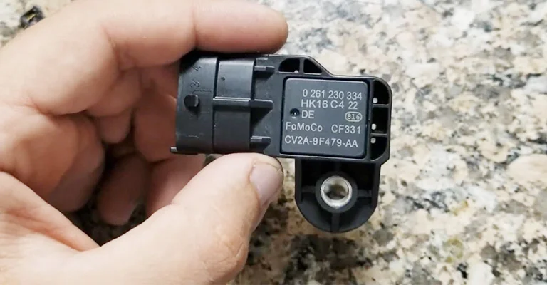
A MAP (Manifold Absolute Pressure) sensor is an electronic device that measures the pressure in the intake manifold of an internal combustion engine. The MAP sensor provides information to the engine control module (ECM) about the engine load, which is used to determine the air-fuel ratio and ignition timing.
The MAP sensor works by measuring the difference between the atmospheric pressure and the pressure inside the intake manifold. The sensor consists of a diaphragm and a strain gauge that detects the deflection of the diaphragm due to the pressure difference. The resulting electrical signal is sent to the ECM, which converts it into a voltage that corresponds to the engine load.
A faulty MAP sensor can cause various engine problems, such as rough idle, reduced power, and increased fuel consumption. Common causes of MAP sensor failure include damaged wiring, clogged vacuum lines, and sensor contamination.
To diagnose a faulty MAP sensor, a mechanic can use a scan tool to check for trouble codes related to the sensor. They can also perform a visual inspection of the sensor and its wiring, and use a vacuum gauge to test the vacuum lines.
Replacing a faulty MAP sensor involves disconnecting the electrical connector and removing the sensor from the intake manifold. The new sensor is then installed and the electrical connector is reconnected. After replacing the sensor, the ECM may need to be reset or reprogrammed to account for the new sensor readings.
The MAP sensor is an important component of an engine's fuel management system. It provides critical information about engine load to the ECM, which allows for optimal fuel delivery and performance. A faulty MAP sensor can cause engine problems, but diagnosis and replacement are relatively straightforward tasks.
MAP Sensor Features
Some of the key features of a MAP (Manifold Absolute Pressure) sensor include:
-
Measurement Range: The sensor should have a wide measurement range, typically from 0 to 5 volts, in order to accurately measure the pressure difference between the intake manifold and atmospheric pressure.
-
Accuracy: The MAP sensor should provide accurate readings even under varying engine load conditions. This is necessary for the engine control module to make precise adjustments to the air-fuel ratio and ignition timing.
-
Durability: The sensor needs to be durable enough to withstand the harsh operating conditions of an internal combustion engine, including heat, vibration, and exposure to contaminants.
-
Response Time: A fast response time is critical for the sensor to provide accurate readings in real time. Slow response times can cause delays in the ECM's response to changes in engine load.
-
Output Signal: The output signal of the MAP sensor should be compatible with the vehicle's engine control system. The most common output signals are voltage or frequency.
-
Diagnostic Capabilities: Modern MAP sensors may also have diagnostic capabilities that allow them to detect and report any faults or malfunctions to the engine control module, which can help with troubleshooting and maintenance.
A high-quality MAP sensor is essential for optimal engine performance and fuel efficiency.
MAP Sensor Applications
MAP sensors are used in a variety of applications where accurate measurement of intake manifold pressure is required. Some common applications include:
-
Fuel Injection Systems: MAP sensors are used to provide input data to the engine control module to determine the correct fuel/air mixture ratio for optimal performance and fuel efficiency.
-
Turbocharger and Supercharger Control: In turbocharged or supercharged engines, MAP sensors are used to monitor the boost pressure and help control the amount of air entering the engine.
-
EGR Valve Control: Exhaust Gas Recirculation (EGR) valves are used to reduce emissions by recirculating exhaust gases back into the engine. MAP sensors are often used to measure the pressure difference across the EGR valve and help regulate its operation.
-
Transmission Shift Pressure Control: In automatic transmissions, MAP sensors are often used to measure the intake manifold pressure and help control the shift points for smoother shifting.
-
Altitude Compensation: Changes in altitude can affect engine performance due to changes in air pressure. MAP sensors can be used to compensate for these changes and maintain consistent engine output.
-
Air/Fuel Ratio Monitoring: In addition to providing input data for fuel injection systems, MAP sensors can also be used to monitor the air/fuel ratio in the engine and help diagnose problems with the fuel system.
MAP Sensor Structure
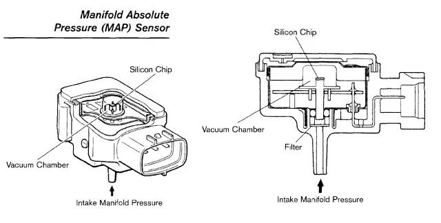
A MAP (Manifold Absolute Pressure) sensor typically consists of a sensing element, an amplifier circuit, and a signal output. The sensing element is usually a thin diaphragm made of silicon, which is exposed to the intake manifold pressure through a small port. As the pressure in the intake manifold changes, the diaphragm deflects, causing a change in resistance or capacitance that is proportional to the pressure.
The amplifier circuit amplifies the signal from the sensing element and converts it into an electrical signal that can be processed by the engine control module. The signal output may be either analog or digital, depending on the vehicle's engine control system.
Some MAP sensors also include temperature compensation circuits to adjust for changes in ambient temperature that could affect the accuracy of the readings. Additionally, some sensors may have built-in diagnostic capabilities to detect and report any faults or malfunctions to the engine control module.
How to use MAP Sensor
-
Determine the location of the sensor: The MAP sensor is typically located on the intake manifold near the throttle body. Consult your vehicle’s service manual for the exact location.
-
Identify the pins/connectors: Before connecting the MAP sensor, identify the pins or connectors for the power supply, ground, and output signal.
-
Connect the MAP sensor to the ECM: Use a wiring harness or connector to connect the MAP sensor to the ECM. Make sure all connections are secure.
-
Calibrate the sensor: Some MAP sensors may require calibration before use. Follow the manufacturer’s instructions for calibrating the sensor.
-
Test the sensor: Start the engine and monitor the output signal from the MAP sensor using a diagnostic tool. Check that the signal varies with changes in engine load and speed.
-
Troubleshoot any issues: If you encounter any issues with the MAP sensor, refer to your vehicle's service manual for troubleshooting tips.
MAP Sensor Types
There are a few different types of MAP sensors that can be used in automotive applications:
-
Absolute pressure MAP sensor: This type of sensor measures the absolute pressure within the intake manifold, referenced to a vacuum.
-
Gauge pressure MAP sensor: This type of sensor measures the pressure difference between the intake manifold and atmospheric pressure, referenced to atmospheric pressure.
-
Differential pressure MAP sensor: This type of sensor measures the difference in pressure between two points, such as the intake manifold and throttle body.
-
Frequency output MAP sensor: This type of sensor outputs a varying frequency signal that corresponds to changes in pressure.
-
Analog voltage output MAP sensor: This type of sensor outputs a varying voltage signal that corresponds to changes in pressure.
The type of MAP sensor used will depend on the specific application and requirements of the engine control system.
Absolute Pressure MAP Sensor VS Differential Pressure MAP Sensor
An Absolute Pressure MAP sensor and a Differential Pressure MAP sensor are two different types of sensors used in automotive applications to measure pressure.
An Absolute Pressure MAP sensor measures the absolute pressure within the intake manifold, referenced to a vacuum. It provides an output signal that is proportional to the absolute pressure inside the engine’s intake system, regardless of outside air pressure. This type of sensor is commonly used in turbocharged or supercharged engines, as it can accurately measure the boost pressure generated by the forced induction system.
On the other hand, a Differential Pressure MAP sensor measures the difference in pressure between two points, such as the intake manifold and throttle body. It provides an output signal that is proportional to the pressure difference between the two points being measured. This type of sensor is commonly used in naturally aspirated engines where there is no forced induction, and the pressure difference between the intake manifold and throttle body is relatively low.
The choice between an Absolute Pressure MAP sensor and a Differential Pressure MAP sensor depends on the specific application and requirements of the engine control system. If the engine has a forced induction system, an Absolute Pressure MAP sensor is preferred, while a Differential Pressure MAP sensor is preferred for naturally aspirated engines.
Absolute pressure MAP sensor VS Gauge pressure MAP sensor
An Absolute Pressure MAP sensor and a Gauge Pressure MAP sensor are two types of pressure sensors used in automotive applications to measure manifold air pressure (MAP).
An Absolute Pressure MAP sensor measures the pressure inside the intake manifold relative to absolute zero pressure (a perfect vacuum), while a Gauge Pressure MAP sensor measures the pressure of the intake manifold relative to atmospheric pressure.
In other words, an Absolute Pressure MAP sensor provides an output signal that represents the total pressure in the intake manifold, regardless of the atmospheric pressure, while a Gauge Pressure MAP sensor provides an output signal that represents the pressure difference between the intake manifold and the atmospheric pressure.
Absolute Pressure MAP sensors are commonly used in forced induction engines where the boost pressure generated by the turbocharger or supercharger needs to be accurately measured. These sensors can provide accurate readings of the total pressure inside the intake manifold, which is essential for proper engine tuning and control.
Gauge Pressure MAP sensors, on the other hand, are commonly used in naturally aspirated engines where the atmospheric pressure is the reference point. These sensors are less expensive than Absolute Pressure MAP sensors and are typically easier to install.
Absolute pressure MAP sensor VS Frequency output MAP sensor
An Absolute Pressure MAP sensor and a Frequency Output MAP sensor are two different types of sensors used to measure manifold air pressure (MAP) in an automotive application.
An Absolute Pressure MAP sensor measures the absolute pressure inside the intake manifold relative to absolute zero pressure (a perfect vacuum) and provides a voltage output signal. The output of an Absolute Pressure MAP sensor is typically a linear voltage signal that represents the absolute pressure value.
On the other hand, a Frequency Output MAP sensor generates a frequency signal that is proportional to the pressure being measured. As the pressure changes, the frequency of the output signal also changes. The output of a Frequency Output MAP sensor is not a voltage or current signal like an Absolute Pressure MAP sensor.
The advantage of a Frequency Output MAP sensor is its ability to provide a high-resolution, non-linear output that can be easily converted into a digital signal. This makes it better suited for use with modern engine control systems that rely on digital signals for accurate control.
In contrast, an Absolute Pressure MAP sensor has a low-resolution output, which is not as suitable for digital signal processing. However, it is more reliable and less susceptible to noise and interference than a Frequency Output MAP sensor.
Therefore, the choice between an Absolute Pressure MAP sensor and a Frequency Output MAP sensor depends on the specific requirements of the engine control system. If high accuracy and reliability are critical, an Absolute Pressure MAP sensor is preferred. On the other hand, if high resolution and compatibility with digital signal processing are important, a Frequency Output MAP sensor may be a better choice.
Absolute pressure MAP sensor VS Analog voltage output MAP sensor
An Absolute Pressure MAP sensor and an Analog Voltage Output MAP sensor are two types of sensors used to measure manifold air pressure (MAP) in an automotive application.
An Absolute Pressure MAP sensor measures the absolute pressure inside the intake manifold relative to absolute zero pressure (a perfect vacuum) and provides a voltage output signal. The output of an Absolute Pressure MAP sensor is typically a linear voltage signal that represents the absolute pressure value.
Analog Voltage Output MAP sensors, on the other hand, measure the pressure in the intake manifold and provide an analog voltage output signal that varies proportionally with the pressure being measured. The output of an Analog Voltage Output MAP sensor is not necessarily a linear voltage signal like an Absolute Pressure MAP sensor, but it can be calibrated to produce a linear output.
The advantage of using an Absolute Pressure MAP sensor over an Analog Voltage Output MAP sensor is that it provides a more accurate and stable measurement of the absolute pressure in the intake manifold. This is because an Absolute Pressure MAP sensor is less susceptible to variations in atmospheric pressure and temperature than an Analog Voltage Output MAP sensor. Additionally, the output signal of an Absolute Pressure MAP sensor is less affected by electrical noise and interference.
However, one disadvantage of using an Absolute Pressure MAP sensor is that it may be more expensive and complex to implement because it requires additional circuitry to convert the absolute pressure reading into a voltage output signal that is compatible with the engine control module.
In contrast, an Analog Voltage Output MAP sensor is generally simpler and less expensive to implement since it outputs a voltage signal directly proportional to the pressure being measured. However, its accuracy and stability may be affected by variations in atmospheric pressure and temperature as well as electrical noise and interference.
Therefore, the choice between an Absolute Pressure MAP sensor and an Analog Voltage Output MAP sensor depends on the specific requirements of the engine control system. If high accuracy and stability are critical, an Absolute Pressure MAP sensor is preferred. On the other hand, if cost and simplicity are important, an Analog Voltage Output MAP sensor may be a better choice.
MAF Sensor VS MAP Sensor
MAF (Mass Air Flow) and MAP (Manifold Absolute Pressure) sensors are both used in modern internal combustion engines to provide information about the amount of air entering the engine. However, they work on different principles and have different applications.
MAF sensors measure the mass of air entering the engine directly, by measuring the amount of air that passes through a heated wire or film element. This information is used by the engine control unit to adjust the fuel injection and ignition timing for optimal performance and fuel efficiency. MAF sensors are commonly used in gasoline engines with electronic fuel injection systems.
On the other hand, MAP sensors measure the absolute pressure inside the intake manifold, which is the duct that carries air and fuel into the cylinders. This information is used by the engine control unit to calculate the engine load and adjust the fuel injection and ignition timing accordingly. MAP sensors are commonly used in diesel engines and some gasoline engines with carburetors or throttle body injection systems.
In general, MAF sensors provide more accurate and responsive measurements of airflow, which can result in better engine performance and fuel economy. However, they are more expensive and sensitive to contamination and damage from dust, oil, and other particles in the air. MAP sensors are less sensitive but more robust and reliable, making them suitable for harsh environments and heavy-duty applications.
MAP Sensor FAQs
Q: What does a MAP sensor do?
A: A MAP (Manifold Absolute Pressure) sensor measures the air pressure inside the intake manifold of an engine. This information is used by the engine control module (ECM) to adjust fuel delivery and ignition timing, ensuring optimal performance and fuel efficiency.
Q: How does a MAP sensor work?
A: A MAP sensor typically consists of a sensing element and an electronic circuit. The sensing element measures the air pressure inside the intake manifold and converts it into an electrical signal, which is then processed by the electronic circuit and sent to the ECM as a voltage signal.
Q: Can a faulty MAP sensor cause a check engine light?
A: Yes, a malfunctioning MAP sensor can trigger the check engine light to come on. Symptoms of a faulty MAP sensor may include rough idling, hesitation or stalling, reduced power or acceleration, and increased fuel consumption.
Q: How can I test a MAP sensor?
A: To test a MAP sensor, you can use a digital multimeter to measure its output voltage while the engine is running. You can also perform a vacuum test to check if the sensor responds to changes in manifold pressure. However, it is recommended to consult the manufacturer's specifications or a professional mechanic for accurate testing procedures.
Q: How often should I replace my MAP sensor?
A: A MAP sensor does not have a specific replacement interval and may last for the life of the vehicle if properly maintained. However, if symptoms of a faulty MAP sensor occur, it is recommended to have it checked and replaced if necessary.
Related Blogs

Categories
Feature Products
AR0230ATSC00XUEAH3-GEVB
BOARD EVAL 2 MP 1/3" CIS HB
$0 VIEW MORE
AR0542MBSC25SUFAH-GEVB
BOARD EVAL 5 MP 1/4" CIS HB
$0 VIEW MORE
FRDM-K22F-SA9500598
FXLC95000CL BOARD WITH FRDM-K22F
$0 VIEW MORE
AR1820HSSC12SHQAH3-GEVB
BOARD EVAL 18 MP 1/2" CIS HB
$0 VIEW MORE
AR0134CSSM00SUEAH-GEVB
BOARD EVAL 1.2 MP 1/3" GS CIS HB
$0 VIEW MORE
LFSTBEB7660
EVAL BOARD FOR MMA7660
$54.373 VIEW MORE
LFSTBEB7361
EVAL BOARD FOR MMA7361L
$0 VIEW MORE
Ai-Thinker ESP32-CAM WiFi BT BLE
ESP32-CAM WiFi+BT SoC 2MP Camera
$7.322 VIEW MORE
ESP32-CAM WiFi BT BLE
ESP32-CAM WiFi+BT SoC 2MP Camera
$6.217 VIEW MORE
RAK1904
WISBLOCK 3-AXIS ACCELERATION SEN
$3.011 VIEW MORE
RAK1901
WISBLOCK TEMPERATURE AND HUMIDIT
$4.199 VIEW MORE
RAK1903
WISBLOCK LIGHT SENSOR
$3.284 VIEW MORE
Subscribe To Receive Discounts And Latest Articles
- Purchase Inquiry: [email protected]
- Support: [email protected]


