Experimental Study of the Crack Predominance of Rock-Like Material Containing Parallel Double Fissures under Uniaxial Compression


School of Resource, Environment and Safety Engineering, Hunan University of Science and Technology, Xiangtan 411201, China
*
Authors to whom correspondence should be addressed.
Sustainability 2020, 12(12), 5188; https://doi.org/10.3390/su12125188
Submission received: 18 May 2020
/
Revised: 18 June 2020
/
Accepted: 23 June 2020
/
Published: 25 June 2020
Abstract
:Fractured rock mass is a relatively complex medium in nature. It plays a key role in various projects, such as geotechnical engineering, mining engineering and tunnel engineering. Especially, the interaction between fissures has a practical function in the guidance of safe production. This paper takes its research object as rock-like material which contains prefabricated parallel double fissures. It studies how the fissures’ length difference and spacing influence the failure of specimens under uniaxial compression, and analyzes them with fracture mechanics theory. The results include two aspects. Firstly, no matter how the length difference and spacing change, the upper fissure always generates new cracks. Secondly, the length difference and spacing produce three effects on the lower fissure. (1) The fissure propagates less obviously as the length difference increases. With the increase to 40mm, the propagation does not occur at all. (2) The decrease of spacing weakens the propagation. As it is reduced to 5 mm, the propagation stops. (3) The crack propagation is more sensitive to length difference than spacing. Regardless of spacing changes, if a length difference is large enough (40 mm or more), the new crack does not expand, while if it is small enough (10 mm or less), propagation always appears.
1. Introduction
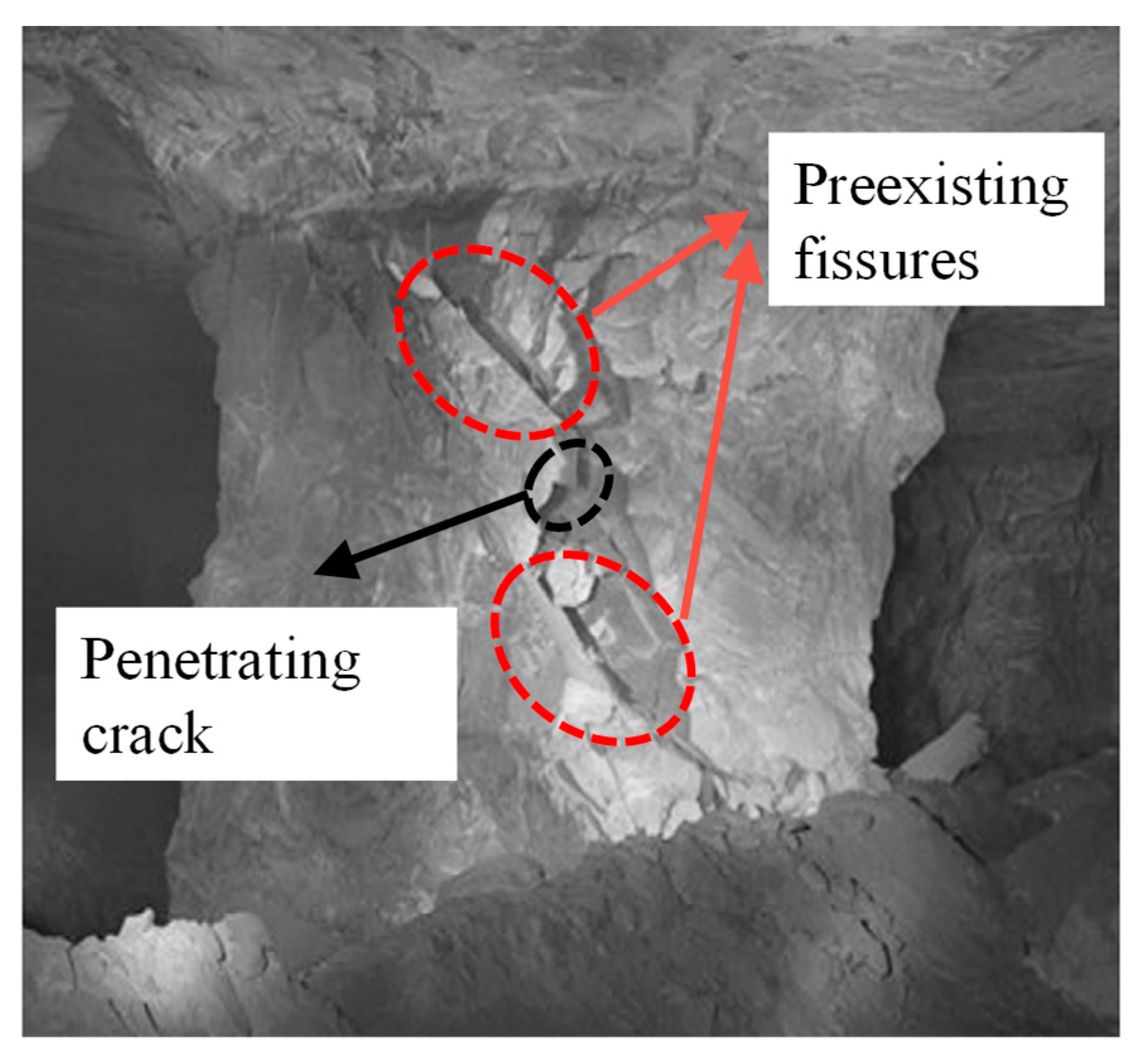
After a long period of geological tectonics, the rock contains internal flaws at multiple scales, such as fissures, joints and faults, varying from the microscopic to macroscopic, which are induced during the initial formation stage of rock masses and successive tectonic motion processes [1,2,3,4]. The propagation and coalescence of these preexisting fissures seriously affect the rocks [5]. They not only degrade its mechanical properties but also induce notch formation and even failure. [1,6,7,8]. As shown in Figure 1, there exist non-persistent and non-coplanar fissures in the pillar. The crack propagation can lead to the penetration of the rock bridge and further damage the stability of the pillar [1,9,10,11]. Hence, it is crucial to understand the fracture behaviors of rock masses containing fissures under axial load for the stability evaluation of underground mining engineering structures.
To figure out how the prefabricated fissure’s form affects its mechanical properties, previous scholars have researched in two ways. Firstly, original rock samples were regarded as research objects. For instance, Yang et al. [12,13,14,15,16,17] used fractured specimens prepared from sandstone, and studied its strength characteristics and prefabricated fissure expansion under uniaxial compression. Zhou et al. [18] used granite containing three pre-existing fissures to research the effects of the coupled thermomechanical and cracking behaviors. Su et al. [19] focused on specimens of longitudinally fractured sandstone, and made a uniaxial compression study of three aspects: strength, deformation and post-failure state.
Secondly, over the past decades, the geological environment has become complex with the increasing depth of excavation [20], which makes it almost impossible to conduct large-scale in-situ tests [6,21,22]. Meanwhile, coring the original rock on-site directly has become very difficult. More importantly, due to the release of stress, the physical and mechanical properties of the collected samples are completely different from the originals [4,23]. Besides this, the internal structure of the rocks is difficult to estimate due to long-term crustal movement [8,23,24]. Since fabricating preexisting fissures in natural rocks is tedious and time-consuming [25], current studies on rock fracture mainly rely on the indoor preparation of specimens using rock-like materials [5,23,26]. For example, Zhou et al. [27] successfully produced resin-based artificial rock specimens with 3D internal flaws with Stereo Lithography and 3-Dimensional Printing techniques. They found that the flaw geometry greatly affects the volumetric and mechanical properties of samples with 3D internal flaws. Zhao et al. [28,29] focused on the strength and the fracture propagation mode of rock-like specimens, which are influenced by the angle and density of fissures. Pu et al. [30] focused on rock-like materials with different fissures opening, and studied the fracture mechanism under uniaxial compression. Based on the results of fractured specimens prepared from concrete materials, Jin et al. [31] analyzed how the angle of the fissure and rock bridge affects the uniaxial compressive strength and failure. Focusing on cross-filling columnar jointed rock materials, Liu et al. [32] investigated the strength and deformation characteristics of rock. Focusing on fractured specimens of a cross joint, Zhang et al. [33] and Qian et al. [34] studied the failure mechanism systematically and worked out how the damage to the form and mechanical properties change with angles of the primary and secondary fissures. The effects of fissure length and ligament angle on the crack propagation were researched by Wang et al. [35]. They further performed simulations with Abaqus, for insight into the stress field change and stress intensity factor. Based on a rock-like sample containing two cross-distributed fissures, Wong et al. [36] studied crack propagation and penetration characteristics under uniaxial compression, and also performed a simulation with Particle Flow Code 2-Dimension.
A summary of the previous studies is as follows. First, the angle and length of the fissures greatly influences the mechanical properties of the samples [37,38]. Second, the strength and failure form of rock masses are not completely decided by joints [39,40]. Third, the fissure spacing can restrain the anisotropy of rocks [21,28,41]. However, there are still deficiencies. Researchers seldom consider the coupling of the fissure length difference and spacing. Besides this, their effects on the mechanical properties of specimens containing parallel double fissures are usually ignored.
Therefore, we conducted both physical and mechanical experiments under uniaxial compression, studied the failure mechanism of the samples with parallel double fissures, and worked out the variation trend of axial stress–strain. We also analyzed the effects of fissure length difference and spacing on crack propagation. Furthermore, based on fracture mechanics theory [8,42,43,44,45], we concluded the propagation rules according to the physical experiments, and verified the experiment setting by comparing the experimental and theoretical results.
2. Laboratory Tests
2.1. Prefabricated Parallel Double Fissures Space Design
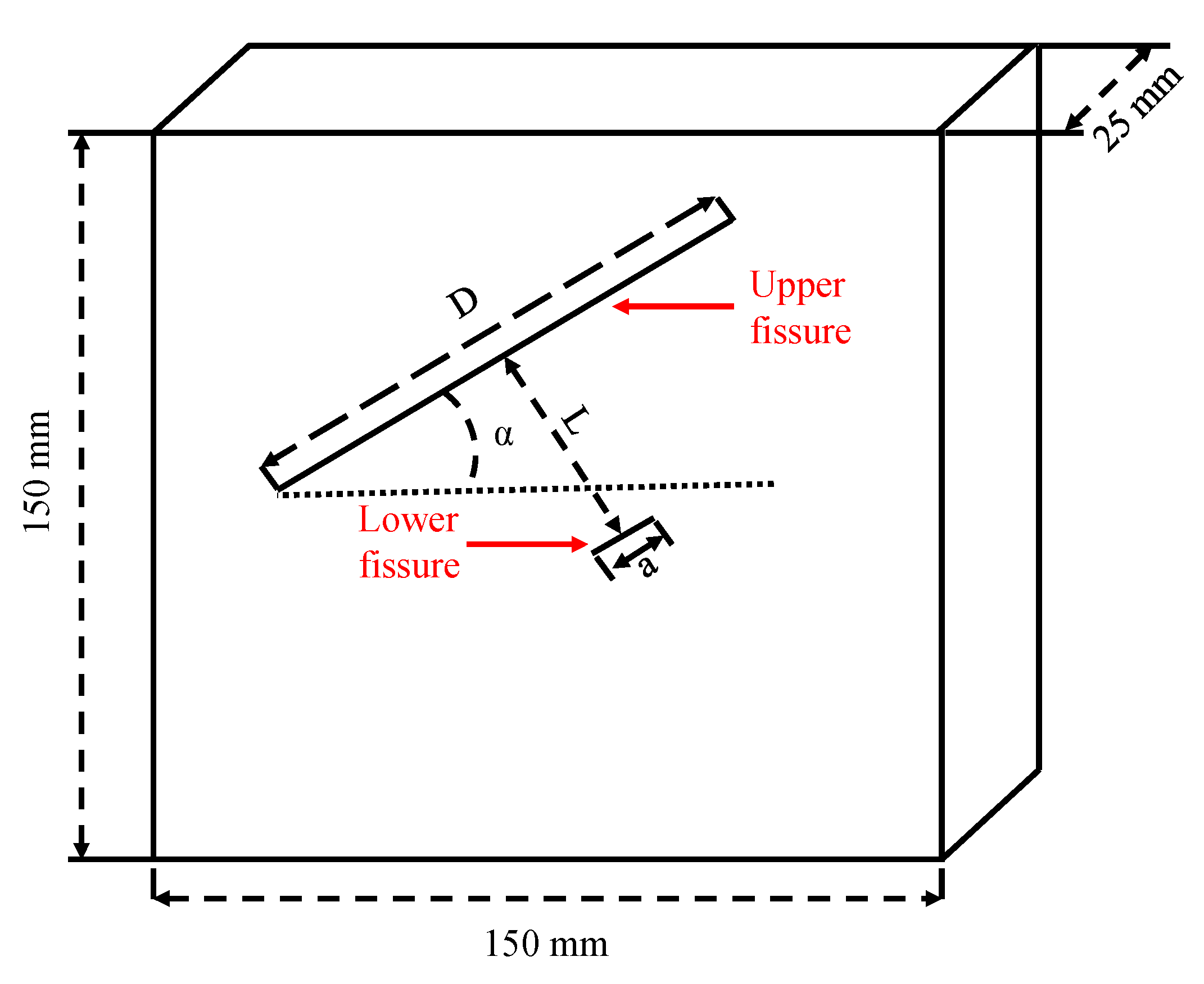
In the preparation of the rock-like fractured specimens, the geometric parameters of prefabricated fissures that needed considering mainly included the angle, length, spacing and width [7,39]. Among them, the upper fissure lengths were set as a, 2a, 3a, 4a and 5a; meanwhile, the spacings were set to 0.5a, a, 1.5a, 2a, 2.5a and 3a (where a = 10mm). All specimens were grouped by the pair-wise combination of their upper fissure length and spacing. Thus, there were 30 groups in total. The detailed parameter settings for each group are shown in Table 1.
Figure 2 illustrates the three-dimensional geometric layout of the prepared specimen. The other geometric parameters were set as: length × width × height = 150 mm × 150 mm × 25 mm. The lower fissure length was always “a = 10 mm”, the angle of the fissure was 30°, and the fissure width was 1 mm.
2.2. Specimen Preparation
The material used to prepare the rock-like fractured specimens was cement mortar, which was composed of Portland cement, silicon powder, standard sand and water at a mass ratio of 1:0.15:1.2:0.35 [5,23,46]. The standard sand acts as the grains in the material, which is of great significance to the frictional behavior of rock-like samples. Portland cement provides the cohesiveness between the grains [47]. After being stirred and mixed, the synthetic materials were poured into the processed steel molds (see Figure 3). Then, we inserted the iron plates into the prescribed slots, and removed them after 10 h to produce the fissures. After 24 h, the hardened samples were taken out of the mold and kept in a special curing room (temperature 20 °C, relative humidity 95%) for 28 days. Their physical and mechanical properties were similar to natural rocks like sandstone [26], and the average value of their static uniaxial compressive strength, tensile strength and elastic modulus of the rock-like materials were 34.8 MPa, 5.2 MPa and 7.33 GPa, respectively.
2.3. Test Equipment
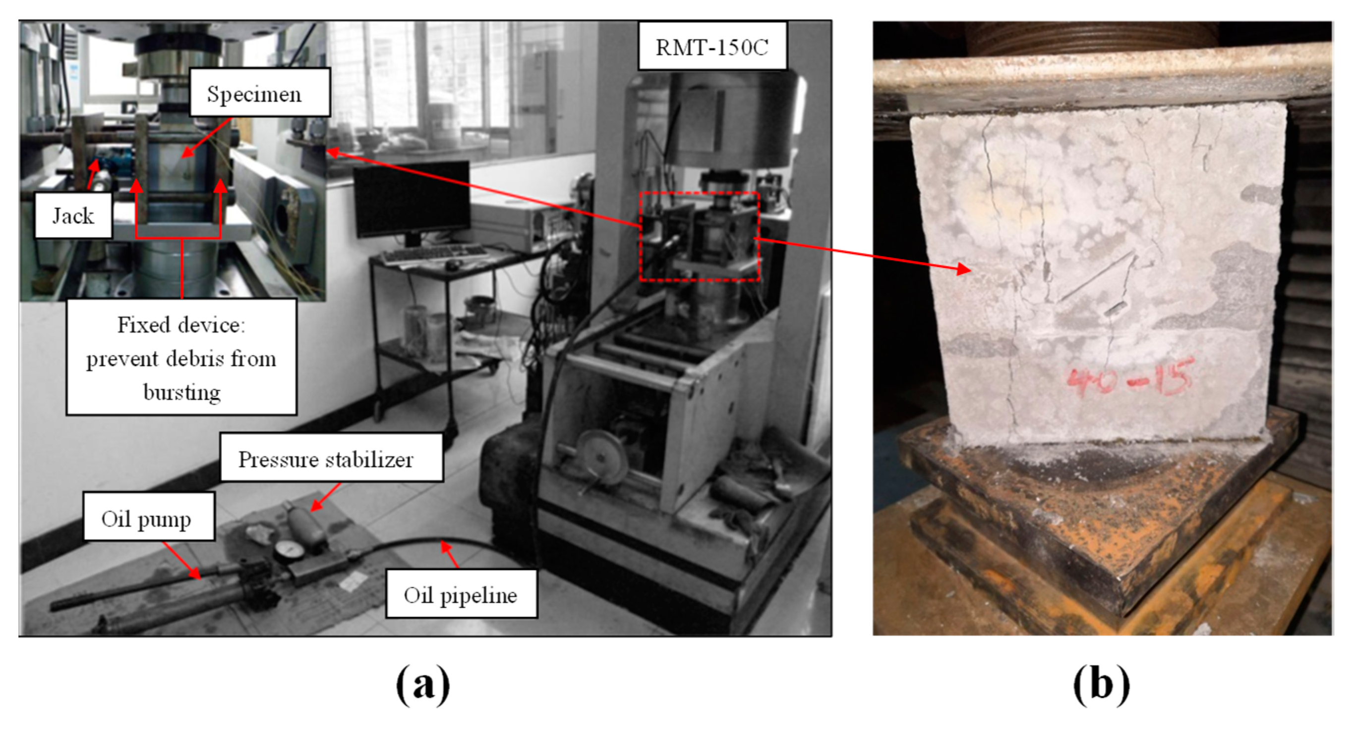
The uniaxial compression tests of the specimens with parallel double fissures were carried out in the rock mechanics laboratory of Hunan University of Science and Technology (Figure 4), using a microcomputer-controlled rock mechanics testing machine (RMT-150c)(Figure 4a). Its measuring error of shear deformation is ≤ ± 0.5%, its displacement error of control precision is ± 0.1%, and its test force error is ± 0.2%. As for axial and lateral control, it supports displacement and force control (shock-free conversion).
To minimize the stress concentration at the end of the specimens, we coated them at their compression face with lubricating oil before loading. Then, we conducted the uniaxial compression test. We loaded the vertical pressure and set the pressurization rate at 100 N/s. At this time, the loading rate was at a low value, which enabled a full record of the whole process of the specimen, including crack initiation, expansion, connection and failure. Figure 4b shows the specimen under uniaxial compression.
3. Laboratory Results and Discussion
3.1. Crack Propagation Mode and External Morphology
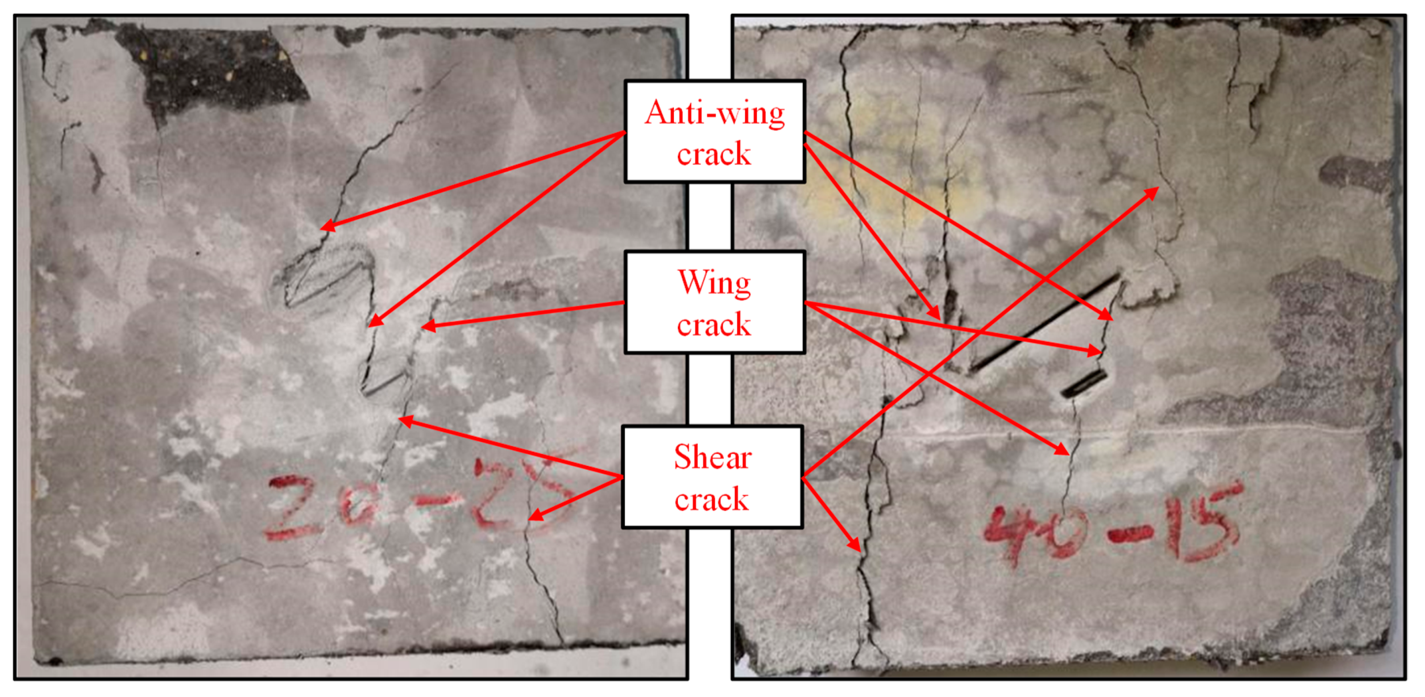
The crack propagation mode and the morphology of the specimen under uniaxial compression are described as follows. With the increase of axial stress, the prefabricated fissures deformed and gradually reached a closed state. At this time, anti-wing-type cracks and small staggers appeared at both ends of the precast fissures. As shown in Figure 5, the wing-type crack propagation did not produce any cataclastic material, and acted like a folded line. The wing-type cracks happened earlier than the others, and propagated along the normal direction. The anti-wing-type cracks also expanded steadily with the increase of the axial stress. Coplanar or oblique shear cracks appeared at the tip of the prefabricated fissures, and expanded synchronously. Their growth rate was relatively stable. The expansion direction formed a certain angle with that of the prefabricated fissure. During the shear crack propagation, it was seen that a few pieces of broken matter fell off. As shown in Figure 5, as the specimen reached complete failure, the shear cracks appeared in step shapes. Therefore, the surface of the specimen became very rough.
3.2. The Axial Stress–Strain Curves of Specimens with Parallel Double Fissures under Uniaxial Compression
Figure 6 shows the axial stress–strain curves of the prefabricated fractured specimens under uniaxial stress, where the length of the upper fissure was 50 mm (Figure 6a). The curve presents as being roughly s-shaped. The prefabricated rock bridge provided the initial strength of the specimen. As the load increased, the crack expanded from the fissure tips. When the rock bridge penetrated, the stress of sample was released. Therefore, the stress–strain curve drops rapidly. Then, the joint of the crack surface generated a new friction force, which meant that the specimen was not immediately destroyed. At this time, the strength of the specimen was residual strength.
Taking specimen No.50-30 as an example, we analyzed each compression process as follows (see Figure 6b).
Under the continuous action of axial stress, the s-shape shows that the property of the specimen varied from plasticity to elasticity, and again to plasticity during the whole process of uniaxial compression. In the loading, each stress drop can lead to energy loss. From a macro perspective, this energy loss manifests as the generation of new cracks, their propagation and the deformation of the sample. This phenomenon conforms to the Griffith energy criterion [48,49].
According to the fracture process of the specimen and the expansion of the cracks, we segmented the stress–strain curve of specimen No.50-30 into the following four stages: internal crack closure (OA), elastic deformation (AB), the crack generation and propagation stage (BC) and the strain-softening stage (CD).
Section OA indicates that the original cracks became dense due to the initial axial load on the specimen. Therefore, this stage is the crack closure stage. At this stage, the tangent slope of the axial stress-strain curve increases continuously, and the curve is concave. Due to the pressure, the original cracks will close, and the stress concentration will appear at the tip of the precast fissure. This will lead to obvious plastic deformation other than macroscopic new crack growths.
Section AB is the elastic deformation stage. In this stage, although some irreversible deformations exist, such as the closure or opening of tiny flaws invisible to the naked eye, the main deformation is elastic, which is subject to Hooke’s law [50]. The axial stress on the specimen is linearly related to the corresponding axial strain, so the curve is almost straight.
Section BC corresponds to the crack generation and propagation stage. When the axial stress is greater than the crack propagation resistance, the stress–strain curve becomes nonlinear, which indicates a plastic deformation. At this stage, more microstructures are damaged and the micro-cracks expand steadily [26,44,47,51]. Meanwhile, the axial strain increases at a reduced rate due to the generation and expansion of micro-cracks. In this figure, point C denotes the stress yield limit. When the axial stress exceeds it, the fracture process will go to the next stage.
Section CD is the strain-softening stage, during which macro-cracks will appear in a large scope. When the axial stress exceeds the peak uniaxial compressive strength, it drops rapidly, but the axial strain changes little. At this time, the specimen is destroyed and loses its carrying capacity. After that, new wing-type cracks appear at the tip of the prefabricated fissure. When propagating to a certain extent, they will continue to expand to the boundary of the specimen, or overlap with the new wing-type cracks or shear cracks produced by another prefabricated fissure. Finally, it penetrates the rock bridge.
3.3. Crack Propagation Mode of Specimens under Uniaxial Compression until Failure
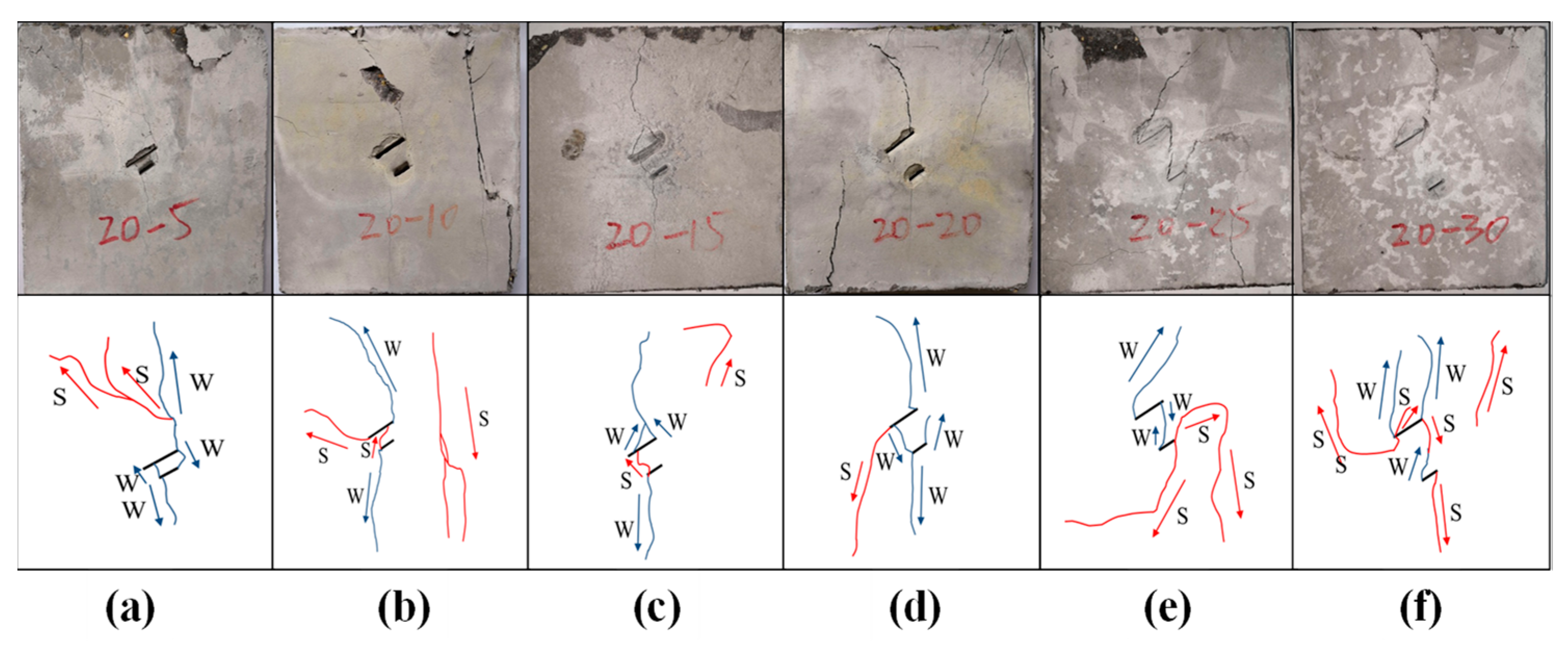
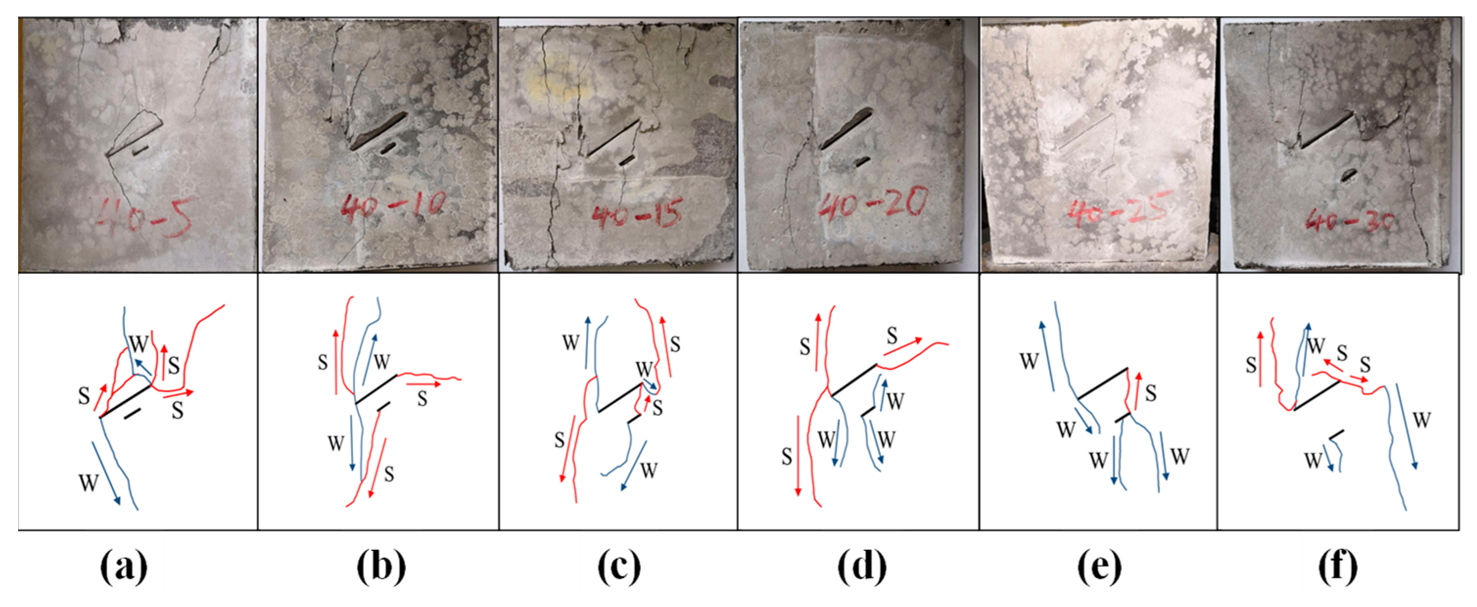
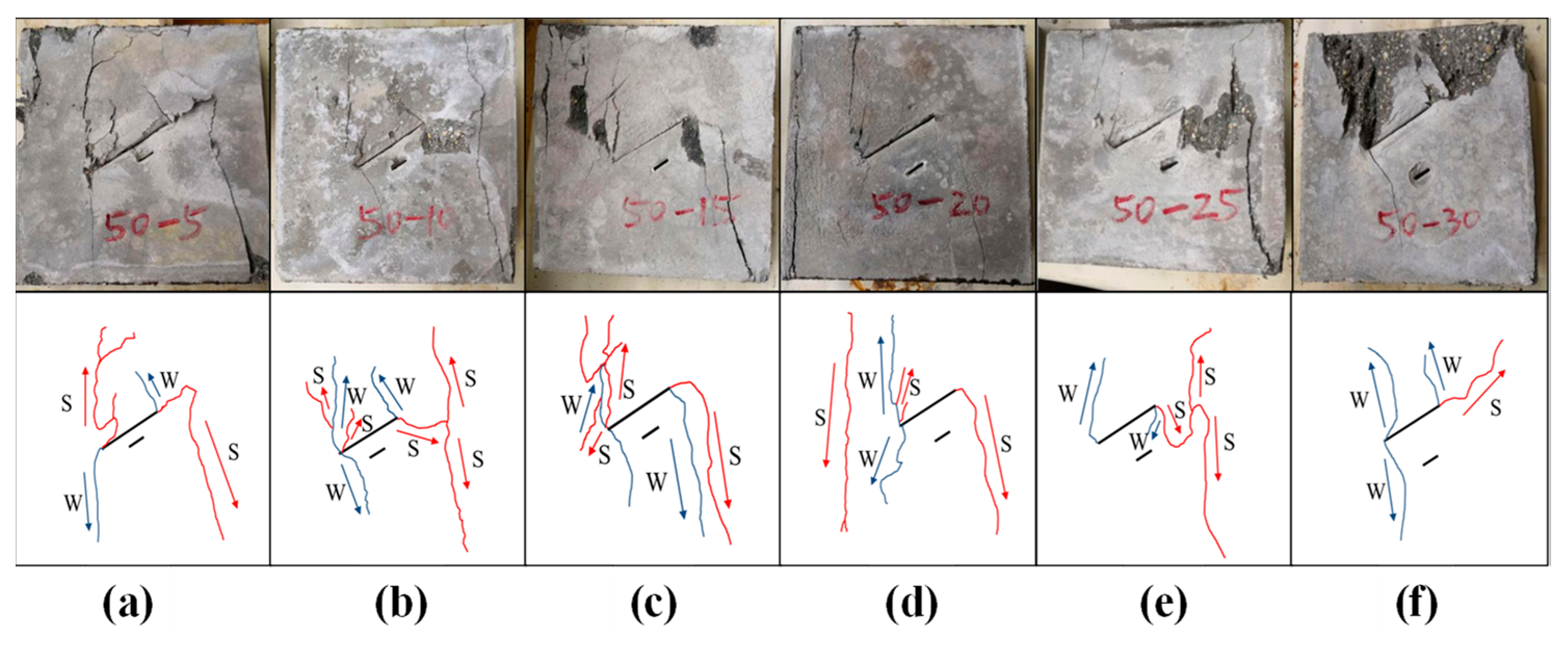
We summarized the crack growth mode of 30 different groups of specimens according to the statistics of the test results, and found that the length increase of the upper fissure leads to the less obvious propagation of the lower (Figure 7, Figure 8, Figure 9, Figure 10 and Figure 11). When the upper fissure is long enough, the propagation does not occur. However, the lower fissure’s extension is more obvious due to the larger fissure spacing. The details are discussed below.
The test results above show that:
- When the length difference is 40 mm, no propagation appears at the lower fissure, but the upper generates new cracks. No matter how the spacing changes, the lower fissure will not expand. The effect of the spacing on the lower propagation can’t be seen by experiments (see Figure 11).
3.4. Mechanical Properties of Crack Propagation
Based on the laboratory results, we made a theoretical analysis of the fracture strength of the rock-like specimens with parallel double fissures, as well as the initiation and propagation of new cracks under the uniaxial compression.
3.4.1. Fracture Strength Analysis of Fissures
Most of the rock masses in nature have flaws, such as macroscopic or microscopic fissures [52]. The failure of rock masses under the external forces is essentially a process of internal fissures cracking, expanding and connecting [46,53]. Under unidirectional stress, new cracks appear in the direction perpendicular to the maximum tensile stress, and develop in a tensile form (see Figure 12).
Where 2a is the length of the prefabricated fissure, σ1 is the maximum principal stress, and β is the angle between the maximum principal stress and the prefabricated fissure (see Figure 13).
Since the friction effect exists on the surface, the effective shear stress τef is [44,54]:
τef refers to the effective shear stress, and μ signifies the friction coefficient.
During the test, the prefabricated fissure under the combined stress of compressive and shear stress did not close. Therefore, the fissure tip stress field is I–II mixed mode. As the infinitesimal of the higher-order is omitted in the calculation, the polar coordinates of the stress field at the tip can be expressed as [44,45,55]:
where θ represents the angle at which an external element deviates from the original fissure tip; r stands for the distance of an external element from the fissure tip; and KI and KII are, respectively, the stress intensity factors of model I and model II fissure tips.
In this experiment, the rock-like specimen was regarded as isotropic material. The rock mass shown in Figure 12 has a linear fissure inside. According to the solution method of stress intensity factor in the theory of fracture mechanics [43,45,56], the stress and displacement components in the isotropic material can be expressed as:
Considering the fissure boundary condition, for the plate with an internal fissure, there is:
To simplify the fissure surface boundary condition, we introduce a new function Ω(z) as:
The plate with internal fissures is a complex connected region problem, in which the single value restriction of the displacement should be considered. That is, when z moves around the fissure once, the displacement difference is zero:
In Equation (13), c can be any closed loop around the fissure. Considering Equation (10), the following equation presents:
Thus, according to equations (7), (8) and (9), the single value restriction of the displacement in Equation (13) can also be shown as follows:
By plugging Equations (10) and (11) into Equations (7)–(9), considering the single value restriction of the displacement in Equation (15), and combining Equations (16) and (17) for the plate with linear fissures, we derive the stress as follows [44,54]:
According to the above derivation of the stress intensity factor in fracture mechanics, together with the stress intensity factor manual [25,44,45,54,58], the stress intensity factor at the fissure tip of parallel double fissures can be obtained as follows:
According to the theory of maximum circumferential tensile stress [44,45,55], the fissure is considered to propagate along the circumferential stress σθθmax (the maximum principal stress) in the corresponding direction of θ, and the following conditions are satisfied:
Equations (4)–(6) differentiate θ. Thus, we can obtain:
making
We have
One of the solutions is
When its solution θ = ±π is substituted into Equation (21), as
it does not satisfy Equation (28).
Furthermore, the crack propagation along the opposite direction has no practical physical significance. Thus, the other set of solutions can be determined by Equation (29):
The deformation is
When KI and KII are not zero, θ0 can be expressed as:
making KII/KI = Kλ, Equation (31) can be written into:
Since the crack does not expand in the opposite direction, |θ| needs to be less than π/2. So we have
The crack propagation will be carried out along the original fissure’s surface at an angle of θ0, whose sign is the opposite of KII.
Based on fracture mechanics theory [25,44,55], the special case of I-II composite cracks are known to be pure I cracks, when KII = 0, θ0 = 0, and Equation (34) can be written as:
From the above, the I-II composite fracture criterion is established, and Equation (35) is substituted into Equation (34) to obtain:
According to Irwin’s formula of displacement at fissure tips [44], the shear fracture toughness formula of a single fracture uses the finite element method to obtain:
Here, τem stands for effective shear stress, and F is the shape factor of time.
3.4.2. Crack Propagation Analysis under Uniaxial Compression
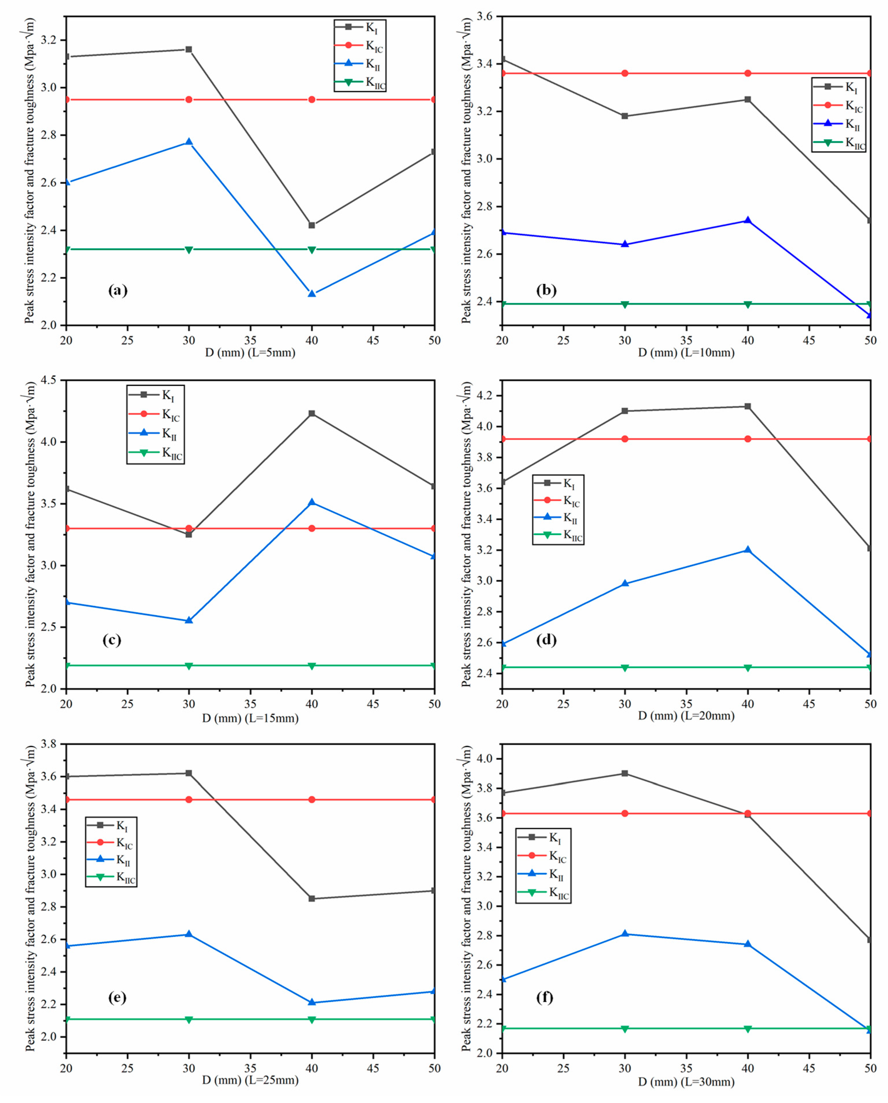
To study the effect of the length difference and spacing of prefabricated fissures on crack propagation, the concept of fracture toughness was introduced based on the theory of fracture mechanics [42,44,45]. In fracture mechanics, stress intensity factors KI (Equation (19)) and KII (Equation (20)) are used to describe the geometric effect of the crack’s size and the external force. KI has a threshold value KIc (Equation (36)), which denotes its fracture toughness. Similarly, stress intensity factor KII also has its fracture toughness, KIIc (Equation (37)). Under certain conditions, KI and KII are mechanical parameters which are related to the size of the loaded specimen, but not to the material itself. Meanwhile, KIc and KIIc are mechanical performance indexes, which are only related to the structure and composition of the material, but not to the sample size and load [54]. When KI or KII at the tip of the analyzed fissure reach its fracture toughness, the unstable expansion will spread rapidly from the prefabricated fissure, and finally result in penetration. The criterion of unstable expansion is given as follows:
or
Table 2 shows the peak uniaxial compressive strength of each test group. Table 3 shows the stress intensity factor of the lower prefabricated fissures KI and KII, as well as their corresponding fracture toughness KIc and KIIc.
As shown in Figure 14a, when L = 5mm and D ≦ 30mm, kI > kIc and kII > kIIc. This means that the new cracks will propagate from the lower fissure. For the specimens with L = 5mm and D > 30 mm, kI < kIc. This indicates that no type I cracks will generate from the lower fissure. Meanwhile, in the specimens with L = 5 mm and D = 50 mm, kII > kIIc. Therefore, when the specimen fails, the lower fissure will expand, and the new crack will grow into type II. This theoretical analysis of this group of specimens is completely consistent with the experiments.
The results of Figure 14 b–f basically agree well with the experimental phenomena. Therefore, they will not be repeated here; please refer to the analysis of Figure 14a above. That is, however, excepting two of the 30 sets of results, as they do not match the experimental phenomena. In the first, when L = 15 and D = 50 mm, kI has a significant drop in value compared to that when D = 40 mm (see Figure 14c). In the second, when L = 20 mm and D = 50 mm, the value of kI drops rapidly, making kI << kIc (see Figure 14d). Considering that the tests have a certain discreteness; their results do not contradict the theoretical formula and/or the laboratory results.
4. Conclusions
In light of the above work, the main conclusions of this paper are as follows:
- According to the uniaxial compression tests, we found that the initial crack runs along the normal direction of the prefabricated fissure. Meanwhile, the new cracks are generated in three forms, including coplanar shear cracks, diagonal shear cracks and wing-type cracks.
- Based on the theoretical study of the fracture mechanics, we deduced the stress intensity factor formula for the tip of the prefabricated lower fissure. By plugging the physical data into the formula, we obtained the theoretical results. The theoretical results agree well with the tests, which confirm the experiment setting.
- Synthesizing the theoretical and laboratory results, we worked out how the fissures’ length difference and spacing affect the crack propagation of the prefabricated fissures.
- No matter how the length difference and spacing change, new cracks are always generated from the upper fissure.
- The lower fissure’s propagation generates cracks less obviously as the length difference increases. With an increase to 40 mm, it does not occur at all
- The decrease of spacing weakens the lower fissure’s propagation. As it was reduced to 5mm, the propagation stopped.
- Compared to the fissure spacing, the length difference has more significant effects on the lower fissure’s propagation.
Author Contributions
Conceptualization, W.C. and W.W.; methodology, W.W. and Y.Z.; software, W.P.; validation, W.C.; formal analysis, W.P.; investigation, W.C.; resources, W.W.; data curation, Y.Z.; writing—original draft preparation, W.C.; writing—review and editing, W.W.; visualization, Y.Z.; supervision, W.C. and W.W.; project administration, W.W. and Y.Z.; funding acquisition, W.W. Y.Z. and W.P. All authors have read and agreed to the published version of the manuscript.
Funding
Research was funded by the National Natural Science Foundation of China (grant number: 51774131, 51774132 and 51974118) and the Natural Science Foundation of Hunan Province (grant number: 2020JJ5188). The APC was funded by the National Natural Science Foundation of China (grant number: 51774132).
Acknowledgments
We thank Daniel Pacurar, Huaiyu Wen, Jie Liu, Wenhao Li and Qiuhong Wu for useful discussions and early contributions to the project, and the reviewers for very helpful and inspiring comments.
Conflicts of Interest
The authors declare no conflict of interest.
References
- Esterhuizen, G.S.; Dolinar, D.R.; Ellenberger, J.L. Pillar strength in underground stone mines in the United States. Int. J. Rock Mech. Min. Sci. 2011, 48, 42–50. [Google Scholar] [CrossRef]
- Dong, W.; Wu, Z.M.; Zhou, X.M.; Wang, N.; Kastiukas, G. An experimental study on crack propagation at rock-concrete interface using digital image correlation technique. Eng. Fract. Mech. 2017, 171, 50–63. [Google Scholar] [CrossRef]
- Yang, S.Q.; Dai, Y.H.; Han, L.J.; Jin, Z.Q. Experimental study on mechanical behavior of brittle marble samples containing different flaws under uniaxial compression. Eng. Fract. Mech. 2009, 76, 1833–1845. [Google Scholar] [CrossRef]
- Zhou, X.P.; Cheng, H.; Feng, Y.F. An Experimental Study of Crack Coalescence Behaviour in Rock-Like Materials Containing Multiple Flaws Under Uniaxial Compression. Rock Mech. Rock Eng. 2014, 47, 1961–1986. [Google Scholar] [CrossRef]
- Feng, P.; Dai, F.; Liu, Y.; Xu, N.W.; Du, H.B. Coupled effects of static-dynamic strain rates on the mechanical and fracturing behaviors of rock-like specimens containing two unparallel fissures. Eng. Fract. Mech. 2019, 207, 237–253. [Google Scholar] [CrossRef]
- Zhou, X.P.; Li, L.H.; Berto, F. Cracking behaviors of rock-like specimens containing two sets of preexisting cross flaws under uniaxial compression. J. Test. Eval. 2019, 47, 838–867. [Google Scholar] [CrossRef]
- Zhou, X.P.; Zhang, J.Z.; Yang, L.H.; Cui, Y.L. Internal morphology of cracking of two 3-d pre-existing cross-embedded flaws under uniaxial compression. Geotech. Test. J. 2018, 41, 20170189. [Google Scholar] [CrossRef]
- Bieniawski, Z.T. Mechanism of brittle fracture of rock: Part II—Experimental studies. Int. J. Rock Mech. Min. Sci. Geomech. Abstr. 1967, 4, 407–423. [Google Scholar] [CrossRef]
- Wu, Q.H.; Li, X.B.; Weng, L.; Li, Q.F.; Zhu, Y.J.; Luo, R. Experimental investigation of the dynamic response of prestressed rockbolt by using an SHPB-based rockbolt test system. Tunn. Undergr. Sp. Technol. 2019, 93, 103088. [Google Scholar] [CrossRef]
- Zhao, Y.L.; Zhang, L.Y.; Wang, W.J.; Wan, W.; Ma, W.H. Separation of elastoviscoplastic strains of rock and a nonlinear creep model. Int. J. Geomech. 2018, 18, 04017129. [Google Scholar] [CrossRef]
- Zhao, Y.L.; Zhang, L.Y.; Wang, W.J.; Tang, J.Z.; Lin, H.; Wan, W. Transient pulse test and morphological analysis of single rock fractures. Int. J. Rock Mech. Min. Sci. 2017, 91, 139–154. [Google Scholar] [CrossRef]
- Yang, S.Q.; Jing, H.W. Strength failure and crack coalescence behavior of brittle sandstone samples containing a single fissure under uniaxial compression. Int. J. Fract. 2011, 168, 227–250. [Google Scholar] [CrossRef]
- Yang, S.Q.; Liu, X.R.; Jing, H.W. Experimental investigation on fracture coalescence behavior of red sandstone containing two unparallel fissures under uniaxial compression. Int. J. Rock Mech. Min. Sci. 2013, 63, 82–92. [Google Scholar] [CrossRef]
- Yang, S.Q.; Liu, X.R. Experimental investigation on dilatancy behavior of marble with pre-existing fissures under different confining pressures. Chin. J. Geotech. Eng. 2012, 34, 2188–2197. [Google Scholar]
- Yang, S.Q.; Yang, Z.; Zhang, P.C.; Tian, W.L. Experiment and peridynamic simulation on cracking behavior of red sandstone containing a single non-straight fissure under uniaxial compression. Theor. Appl. Fract. Mech. 2020, 108, 102637. [Google Scholar] [CrossRef]
- Yang, S.Q. Crack coalescence behavior of brittle sandstone samples containing two coplanar fissures in the process of deformation failure. Eng. Fract. Mech. 2011, 78, 3059–3081. [Google Scholar] [CrossRef]
- Yang, S.Q.; Huang, Y.H.; Ranjith, P.G. Failure mechanical and acoustic behavior of brine saturated-sandstone containing two pre-existing flaws under different confining pressures. Eng. Fract. Mech. 2018, 193, 108–121. [Google Scholar] [CrossRef]
- Zhou, X.P.; Li, G.Q.; Ma, H.C. Real-time experiment investigations on the coupled thermomechanical and cracking behaviors in granite containing three pre-existing fissures. Eng. Fract. Mech. 2020, 224, 106797. [Google Scholar] [CrossRef]
- Su, H.J.; Jing, H.W.; Zhao, H.H. Experimental study on the influence of longitudinal fissure on mechanics charac teristic of sandstone. J. Min. Saf. Eng. 2014, 31, 644–649. [Google Scholar]
- Miao, S.; Pan, P.-Z.; Wu, Z.; Li, S.; Zhao, S. Fracture analysis of sandstone with a single filled flaw under uniaxial compression. Eng. Fract. Mech. 2018, 204, 319–343. [Google Scholar] [CrossRef]
- Zhang, B.; Li, S.; Yang, X.; Xia, K.; Liu, J.; Guo, S.; Wang, S. The coalescence and strength of rock-like materials containing two aligned X- type flaws under uniaxial compression. Geomech. Eng. 2019, 17, 47–56. [Google Scholar]
- Kou, M.; Liu, X.; Tang, S.; Wang, Y. 3-D X-ray computed tomography on failure characteristics of rock-like materials under coupled hydro-mechanical loading. Theor. Appl. Fract. Mech. 2019, 104, 102396. [Google Scholar] [CrossRef]
- Ha, Y.D.; Lee, J.; Hong, J.-W. Fracturing patterns of rock-like materials in compression captured with peridynamics. Eng. Fract. Mech. 2015, 144, 176–193. [Google Scholar] [CrossRef]
- Theocaris, P.S. Ductile branching modes in stable propagating cracks: An experimental study. Eng. Fract. Mech. 1990, 36, 477–493. [Google Scholar] [CrossRef]
- Wei, M.D.; Dai, F.; Xu, N.W.; Zhao, T. Stress intensity factors and fracture process zones of ISRM-suggested chevron notched specimens for mode I fracture toughness testing of rocks. Eng. Fract. Mech. 2016, 168, 174–189. [Google Scholar] [CrossRef]
- Einstein, H.H.; Hirschfeld, R.C.; Nelson, R.A.; Bruhn, R.W. Model Studies of Jointed-Rock Behavior. In Proceedings of the 11th U.S. Symposium on Rock Mechanics (USRMS), Berkeley, CA, USA, 16–19 June 1969; p. 22. [Google Scholar]
- Zhou, T.; Zhu, J.B.; Ju, Y.; Xie, H.P. Volumetric fracturing behavior of 3D printed artificial rocks containing single and double 3D internal flaws under static uniaxial compression. Eng. Fract. Mech. 2019, 205, 190–204. [Google Scholar] [CrossRef]
- Zhao, Y.L.; Zhang, L.Y.; Wang, W.J.; Pu, C.Z.; Wan, W.; Tang, J.Z. Cracking and Stress–Strain Behavior of Rock-Like Material Containing Two Flaws Under Uniaxial Compression. Rock Mech. Rock Eng. 2016, 49, 2665–2687. [Google Scholar] [CrossRef]
- Zhao, Y.L.; Wan, W.; Wang, W.J.; Wang, M.; Peng, Q.Y. Fracture experiments on ordered multi-crack body in rock-like materials under uniaxial compression and numerical simulation of wing cracks. Yantu Gongcheng Xuebao/Chin. J. Geotech. Eng. 2013, 35, 2097–2109. [Google Scholar]
- Pu, C.Z.; Cao, P.; Zhao, Y.L.; Zhang, X.Y.; Liu, Y.K. Numerical analysis and strength experiment of rock-like materials with multi-fissures under uniaxial compression. Rock Soil Mech. 2010, 31, 3661–3666. [Google Scholar]
- Jin, J.; Cao, P.; Pu, C. Influence of flaw parameters on damage mode and strength of rock-like materials. J. Cent. South Univ. 2014, 45, 529–535. [Google Scholar]
- Liu, X.; Liu, A.; Li, X. Experimental study of columnar jointed sandstone-like material with preset filling. Chin. J. Rock Mech. Eng. 2014, 33, 772–777. [Google Scholar]
- Zhang, B.; Li, S.C.; Yang, X.Y.; Zhang, D.F.; Yang, W.M. Uniaxial compression tests on mechanical properties of rock mass similar material with cross-cracks. Yantu Lixue/Rock Soil Mech. 2012, 33, 3674–3679. [Google Scholar]
- Qian, X.K.; Liang, Z.Z.; Liao, Z.Y.; Wang, K. Numerical investigation of dynamic fracture in rock specimens containing a pre-existing surface flaw with different dip angles. Eng. Fract. Mech. 2020, 223, 106675. [Google Scholar] [CrossRef]
- Wang, Y.; Zhou, X.; Xu, X. Numerical simulation of propagation and coalescence of flaws in rock materials under compressive loads using the extended non-ordinary state-based peridynamics. Eng. Fract. Mech. 2016, 163, 248–273. [Google Scholar] [CrossRef]
- Wong, L.N.Y.; Zhang, X.P. Crack coalescence study based on the bonded-particle model approach. In Proceedings of the ISRM International Symposium-EUROCK 2012, Stockholm, Sweden, 28–30 May 2012; p. 10. [Google Scholar]
- Modiriasari, A.; Jiang, L.; Yoon, H.; Bobet, A.; Pyrak-Nolte, L.J. Effect of Layering on Cracking Initiation and Propagation under Uniaxial Compression. In Proceedings of the Agu Fall Meeting, New Orleans, LA, USA, 11–15 December 2017. [Google Scholar]
- Afolagboye, L.O.; He, J.; Wang, S. Crack Initiation and Coalescence Behavior of Two Non-parallel Flaws. Geotech. Geol. Eng. 2017, 36, 105–133. [Google Scholar] [CrossRef]
- Zhou, X.P.; Zhang, J.Z.; Wong, L.N.Y. Experimental Study on the Growth, Coalescence and Wrapping Behaviors of 3D Cross-Embedded Flaws Under Uniaxial Compression. Rock Mech. Rock Eng. 2018, 51, 1379–1400. [Google Scholar] [CrossRef]
- Afolagboye, L.O.; He, J.; Wang, S. Experimental study on cracking behaviour of moulded gypsum containing two non-parallel overlapping flaws under uniaxial compression. J. Mech. 2017, 33, 394–405. [Google Scholar] [CrossRef]
- Wang, Y.; Zhou, X.; Shou, Y. The modeling of crack propagation and coalescence in rocks under uniaxial compression using the novel conjugated bond-based peridynamics. Int. J. Mech. Sci. 2017, 614–643. [Google Scholar] [CrossRef]
- Singh, R.N.; Whittaker, B.N.; Sun, G. Rock fracture mechanics. In Rock Fracture Mechanics; Elsevier: Amsterdam, The Netherlands, 1992; p. 275. [Google Scholar]
- Xiang, W.; Yang, H.T. The method of caustics applied in fracture mechanics(determination of stress intensity factor KI). Acta Mech. Solida Sinica 1984, 23, 498–548. [Google Scholar]
- Irwin, G.R. Linear fracture mechanics, fracture transition, and fracture control. Eng. Fract. Mech. 1968, 1, 241–257. [Google Scholar] [CrossRef]
- Marquis, G. Failure Modes and Fatigue Strength of Improved HSS Welds. Eng. Fract. Mech. 2001, 77, 2051–2062. [Google Scholar] [CrossRef]
- Wang, M.; Wan, W. A new empirical formula for evaluating uniaxial compressive strength using the Schmidt hammer test. Int. J. Rock Mech. Min. Sci. 2019, 123, 104094. [Google Scholar] [CrossRef]
- Xie, H.P.; Li, L.Y.; Peng, R.D.; Ju, Y. Energy analysis and criteria for structural failure of rocks. J. Rock Mech. Geotech. Eng. 2009, 1, 11–20. [Google Scholar] [CrossRef] [Green Version]
- Zhao, Y. Griffith’s criterion for mixed mode crack propagation. Eng. Fract. Mech. 1987, 26, 683–689. [Google Scholar] [CrossRef]
- Margolin, L.G. A generalized Griffith criterion for crack propagation. Eng. Fract. Mech. 1984, 19, 539–543. [Google Scholar] [CrossRef]
- Rychlewski, J. On Hooke’s law. J. Appl. Math. Mech. 1984, 48, 303–314. [Google Scholar] [CrossRef]
- Zhao, Y.L.; Peng, Q.Y.; Wan, W.; Wang, W.J.; Zhang, S.G. Seepage-fracture coupling mechanism of rock masses cracking propagation under high hydraulic pressure and numerical verification. Yantu Lixue/Rock Soil Mech. 2014, 35, 556–564. [Google Scholar]
- Wu, Q.H.; Chen, L.; Shen, B.T.; Dlamini, B.; Li, S.Q.; Zhu, Y.J. Experimental Investigation on Rockbolt Performance Under the Tension Load. Rock Mech. Rock Eng. 2019, 52, 4605–4618. [Google Scholar] [CrossRef]
- Zhao, Y.L.; Wang, Y.X.; Wang, W.J.; Tang, L.; Liu, Q.; Cheng, G. Modeling of rheological fracture behavior of rock cracks subjected to hydraulic pressure and far field stresses. Theor. Appl. Fract. Mech. 2019, 101, 59–66. [Google Scholar] [CrossRef]
- Wang, M.; Zhu, Z.M.; Dong, Y.Q.; Zhou, L. Study of mixed-mode I/II fractures using single cleavage semicircle compression specimens under impacting loads. Eng. Fract. Mech. 2017, 177, 33–44. [Google Scholar] [CrossRef]
- Zhao, Y.L.; Zhang, L.Y.; Liao, J.; Wang, W.J.; Liu, Q.; Tang, L.M. Experimental study of fracture toughness and subcritical crack growth of three rocks under different environments. Int. J. Geomech. 2020, 20, 04020128. [Google Scholar] [CrossRef]
- Kpegba, K.W.; Ottavy, N.; Souchet, R. Stress intensity factors in two-dimensional crack problems by using the Superimposed Meshes Method. Eng. Fract. Mech. 1996, 54, 113–125. [Google Scholar] [CrossRef]
- Hooft, G.T. Dimensional regularization and the renormalization group. Nucl. Phys. 1973, 61, 455–468. [Google Scholar] [CrossRef] [Green Version]
- Pal, S.; Ibrahim, R.N.; Raman, R.K.S. Threshold stress intensity factor and crack growth rate for stress corrosion cracking of simulated heat affected zone in caustic solution. Eng. Fract. Mech. 2011, 78, 13–26. [Google Scholar] [CrossRef]
- Zhao, Y.L.; Wang, Y.X.; Wang, W.J.; Wang, W.J.; Tang, J.Z. Modeling of non-linear rheological behavior of hard rock using triaxial rheological experiment. Int. J. Rock Mech. Min. Sci. 2017, 93, 66–75. [Google Scholar] [CrossRef]
Figure 1.
Crack propagation of preexisting fissures [1].
Figure 1.
Crack propagation of preexisting fissures [1].

Figure 2.
Designed drawing of the prefabricated rock-like fractured specimen. (a: length of the lower fissure; D: length of upper fissure; L: fissure spacing; α: fissure angle).
Figure 2.
Designed drawing of the prefabricated rock-like fractured specimen. (a: length of the lower fissure; D: length of upper fissure; L: fissure spacing; α: fissure angle).

Figure 3.
Preparation of prefabricated parallel double fissure specimens.

Figure 4.
(a) RMT-150C: rock mechanics test system; (b) the typical failure pattern of the sample.

Figure 5.
Morphology of crack propagation.

Figure 6.
Axial stress–strain curves of parallel double fissure rock specimens (D = 50 mm): (a) all fissure spacings; (b) the fissure spacing of 30 mm.
Figure 6.
Axial stress–strain curves of parallel double fissure rock specimens (D = 50 mm): (a) all fissure spacings; (b) the fissure spacing of 30 mm.

Figure 7.
The crack penetration mode of rock-like specimens with D = 10 mm: (a) L = 5 mm; (b) L = 10 mm; (c) L = 15 mm; (d) L = 20 mm; (e) L = 25 mm; (f) L = 30 mm (W: wing-type crack; S: shear crack; →: crack development direction).
Figure 7.
The crack penetration mode of rock-like specimens with D = 10 mm: (a) L = 5 mm; (b) L = 10 mm; (c) L = 15 mm; (d) L = 20 mm; (e) L = 25 mm; (f) L = 30 mm (W: wing-type crack; S: shear crack; →: crack development direction).

Figure 8.
The crack penetration mode of rock-like specimens with D = 20 mm: (a) L = 5 mm; (b) L = 10 mm; (c) L = 15 mm; (d) L = 20 mm; (e) L = 25 mm; (f) L = 30 mm (W: wing-type crack; S: shear crack; →: crack development direction).
Figure 8.
The crack penetration mode of rock-like specimens with D = 20 mm: (a) L = 5 mm; (b) L = 10 mm; (c) L = 15 mm; (d) L = 20 mm; (e) L = 25 mm; (f) L = 30 mm (W: wing-type crack; S: shear crack; →: crack development direction).

Figure 9.
The crack penetration mode of rock-like specimens with D = 30 mm: (a) L = 5 mm; (b) L = 10 mm; (c) L = 15 mm; (d) L = 20 mm; (e) L = 25 mm; (f) L = 30 mm (W: wing-type crack; S: shear crack; →: crack development direction).
Figure 9.
The crack penetration mode of rock-like specimens with D = 30 mm: (a) L = 5 mm; (b) L = 10 mm; (c) L = 15 mm; (d) L = 20 mm; (e) L = 25 mm; (f) L = 30 mm (W: wing-type crack; S: shear crack; →: crack development direction).

Figure 10.
The crack penetration mode of rock-like specimens with D = 40 mm: (a) L = 5 mm; (b) L = 10 mm; (c) L = 15 mm; (d) L = 20 mm; (e) L = 25 mm; (f) L = 30 mm (W: wing-type crack; S: shear crack; →: crack development direction).
Figure 10.
The crack penetration mode of rock-like specimens with D = 40 mm: (a) L = 5 mm; (b) L = 10 mm; (c) L = 15 mm; (d) L = 20 mm; (e) L = 25 mm; (f) L = 30 mm (W: wing-type crack; S: shear crack; →: crack development direction).

Figure 11.
The crack penetration mode of rock-like specimens with D = 50 mm: (a) L = 5 mm; (b) L = 10 mm; (c) L = 15 mm; (d) L = 20 mm; (e) L = 25 mm; (f) L = 30 mm (W: wing-type crack; S: shear crack; →: crack development direction).
Figure 11.
The crack penetration mode of rock-like specimens with D = 50 mm: (a) L = 5 mm; (b) L = 10 mm; (c) L = 15 mm; (d) L = 20 mm; (e) L = 25 mm; (f) L = 30 mm (W: wing-type crack; S: shear crack; →: crack development direction).

Figure 12.
Stress analysis diagram of fractured rock mass under unidirectional stress.

Figure 13.
Non-closed fissure stress superposition diagram: (a) Type I-II composite crack; (b) Type I crack; (c) Type II crack.
Figure 13.
Non-closed fissure stress superposition diagram: (a) Type I-II composite crack; (b) Type I crack; (c) Type II crack.

Figure 14.
Relationship between peak uniaxial compressive strength intensity factor and fracture toughness: (a) L = 5 mm, (b) L = 10 mm, (c) L = 15 mm, (d) L = 20 mm, (e) L = 25 mm, (f) L = 30 mm.
Figure 14.
Relationship between peak uniaxial compressive strength intensity factor and fracture toughness: (a) L = 5 mm, (b) L = 10 mm, (c) L = 15 mm, (d) L = 20 mm, (e) L = 25 mm, (f) L = 30 mm.


Table 1.
Detailed information about prefabricated fractured specimens.
| Specimen Number (D-L) | Upper Fissure Length (mm) | Fissure Spacing (mm) | Specimen Number (D-L) | Upper Fissure Length (mm) | Fissure Spacing (mm) |
|---|---|---|---|---|---|
| 10–5 | a | 0.5a | 30–20 | 3a | 2a |
| 10–10 | a | a | 30–25 | 3a | 2.5a |
| 10–15 | a | 1.5a | 30–30 | 3a | 3a |
| 10–20 | a | 2a | 40–5 | 4a | 0.5a |
| 10–25 | a | 2.5a | 40–10 | 4a | a |
| 10–30 | a | 3a | 40–15 | 4a | 1.5a |
| 20–5 | 2a | 0.5a | 40–20 | 4a | 2a |
| 20–10 | 2a | a | 40–25 | 4a | 2.5a |
| 20–15 | 2a | 1.5a | 40–30 | 4a | 3a |
| 20–20 | 2a | 2a | 50–5 | 5a | 0.5a |
| 20–25 | 2a | 2.5a | 50–10 | 5a | a |
| 20–30 | 2a | 3a | 50–15 | 5a | 1.5a |
| 30–5 | 3a | 0.5a | 50–20 | 5a | 2a |
| 30–10 | 3a | a | 50–25 | 5a | 2.5a |
| 30–15 | 3a | 1.5a | 50–30 | 5a | 3a |
Table 2.
Peak uniaxial compressive strength of each test group.
| Specimen Number (D-L) | σmax (Mpa) | Specimen Number (D-L) | σmax (Mpa) | Specimen Number (D-L) | σmax (Mpa) | Specimen Number (D-L) | σmax (Mpa) |
|---|---|---|---|---|---|---|---|
| 10–5 | 41.30 | 40–10 | 24.38 | 20–20 | 32.56 | 40–25 | 19.17 |
| 20–5 | 32.70 | 50–10 | 18.60 | 30–20 | 30.68 | 50–25 | 18.18 |
| 30–5 | 28.50 | 10–15 | 39.10 | 40–20 | 28.51 | 10–30 | 39.15 |
| 40–5 | 18.95 | 20–15 | 34.00 | 50–20 | 20.08 | 20–30 | 31.53 |
| 50–5 | 19.10 | 30–15 | 26.24 | 10–25 | 38.35 | 30–30 | 28.87 |
| 10–10 | 43.61 | 40–15 | 31.25 | 20–25 | 32.26 | 40–30 | 24.38 |
| 20–10 | 33.85 | 50–15 | 24.41 | 30–25 | 27.08 | 50–30 | 17.14 |
| 30–10 | 27.14 | 10–20 | 43.92 |
Table 3.
Stress intensity factor and fracture toughness of prefabricated lower fissure tips under peak uniaxial compressive strength.
Table 3.
Stress intensity factor and fracture toughness of prefabricated lower fissure tips under peak uniaxial compressive strength.
| Specimen Number (D-L) | ||||
|---|---|---|---|---|
| 20–5 | 3.13 | 2.95 | 2.60 | 2.32 |
| 30–5 | 3.16 | 2.95 | 2.77 | 2.32 |
| 40–5 | 2.42 | 2.95 | 2.13 | 2.32 |
| 50–5 | 2.73 | 2.95 | 2.39 | 2.32 |
| 20–10 | 3.42 | 3.36 | 2.69 | 2.39 |
| 30–10 | 3.18 | 3.36 | 2.64 | 2.39 |
| 40–10 | 3.25 | 3.36 | 2.74 | 2.39 |
| 50–10 | 2.74 | 3.36 | 2.34 | 2.39 |
| 20–15 | 3.62 | 3.30 | 2.70 | 2.19 |
| 30–15 | 3.25 | 3.30 | 2.55 | 2.19 |
| 40–15 | 4.23 | 3.30 | 3.51 | 2.19 |
| 50–15 | 3.64 | 3.30 | 3.07 | 2.19 |
| 20–20 | 3.64 | 3.92 | 2.59 | 2.44 |
| 30–20 | 4.10 | 3.92 | 2.98 | 2.44 |
| 40–20 | 4.13 | 3.92 | 3.20 | 2.44 |
| 50–20 | 3.21 | 3.92 | 2.52 | 2.44 |
| 20–25 | 3.60 | 3.46 | 2.56 | 2.11 |
| 30–25 | 3.62 | 3.46 | 2.63 | 2.11 |
| 40–25 | 2.85 | 3.46 | 2.21 | 2.11 |
| 50–25 | 2.90 | 3.46 | 2.28 | 2.11 |
| 20–30 | 3.77 | 3.63 | 2.50 | 2.17 |
| 30–30 | 3.90 | 3.63 | 2.81 | 2.17 |
| 40–30 | 3.62 | 3.63 | 2.74 | 2.17 |
| 50–30 | 2.77 | 3.63 | 2.15 | 2.17 |
© 2020 by the authors. Licensee MDPI, Basel, Switzerland. This article is an open access article distributed under the terms and conditions of the Creative Commons Attribution (CC BY) license (http://creativecommons.org/licenses/by/4.0/).
Share and Cite
MDPI and ACS Style
Chen, W.; Wan, W.; Zhao, Y.; Peng, W. Experimental Study of the Crack Predominance of Rock-Like Material Containing Parallel Double Fissures under Uniaxial Compression. Sustainability 2020, 12, 5188. https://doi.org/10.3390/su12125188
AMA Style
Chen W, Wan W, Zhao Y, Peng W. Experimental Study of the Crack Predominance of Rock-Like Material Containing Parallel Double Fissures under Uniaxial Compression. Sustainability. 2020; 12(12):5188. https://doi.org/10.3390/su12125188
Chicago/Turabian StyleChen, Wei, Wen Wan, Yanlin Zhao, and Wenqing Peng. 2020. "Experimental Study of the Crack Predominance of Rock-Like Material Containing Parallel Double Fissures under Uniaxial Compression" Sustainability 12, no. 12: 5188. https://doi.org/10.3390/su12125188
Note that from the first issue of 2016, this journal uses article numbers instead of page numbers. See further details here.