
Trombe Wall System’s Thermal Energy Output Analysis at a Factory Building


1
Department of Heat Engineering and Technology, Faculty of Civil Engineering, Riga Technical University, LV-1048 Riga, Latvia
2
Department of Building Materials and Products, Faculty of Civil Engineering, Riga Technical University, LV-1048 Riga, Latvia
*
Authors to whom correspondence should be addressed.
Energies 2023, 16(4), 1887; https://doi.org/10.3390/en16041887
Submission received: 30 December 2022
/
Revised: 7 February 2023
/
Accepted: 9 February 2023
/
Published: 14 February 2023
(This article belongs to the Section A2: Solar Energy and Photovoltaic Systems)
Abstract
:Solar energy utilization for covering and offsetting the heating loads of buildings, is a sustainable way to reduce energy consumption (electricity, gas, etc.) for space heating. As such, a Trombe wall technology is a classic passive solar heating system used in buildings, that can be modified and applied to cold climate regions. This work presents a case study on a Trombe wall’s application in relation to its thermal energy output for space heating purposes at a factory building in central Latvia. The solar radiation and temperature measurements were carried out throughout the months of June to October. The results show that the examined wall has a monthly energy yield of 120 to 290 kWh, suggesting that Trombe wall systems are applicable as a secondary space heating source in cold climate regions such as northern Europe, however, a number of design and structural aspects have to be thoroughly considered.
1. Introduction
1.1. Trombe Wall Technology
When using passive solar energy for space heating, it should be taken into account that the amount of solar thermal energy varies throughout the year. The greatest heat radiation is available in the summer, when premises require cooling rather than heating. In order to reduce the cooling load, it is necessary to limit the area of west-facing windows, because the highest solar radiation is observed during the day, in addition, a heat-resistant building will have accumulated the solar radiation received in the first half of the day in its structural elements, as well as by creating natural or artificial shading elements [1,2,3]. The Latvian climate is also well suited for the passive use of solar energy, both for heating and cooling [4]. However, Trombe walls have not been considered.
Utilizing and storing solar energy to cover and offset building heating loads is an innovative and environmentally friendly way to reduce a building’s energy consumption (electricity, gas, etc.) for space heating [5,6].
Trombe walls are a traditional passive solar heating system for buildings, and in the summer they can be used to cool buildings [7,8]. In recent decades, the Trombe wall, as an effective passive solar building facade system, has received considerable attention. Its applications are rather simple and cost-effective, and it is suitable for a wide range of latitudes [2,9].
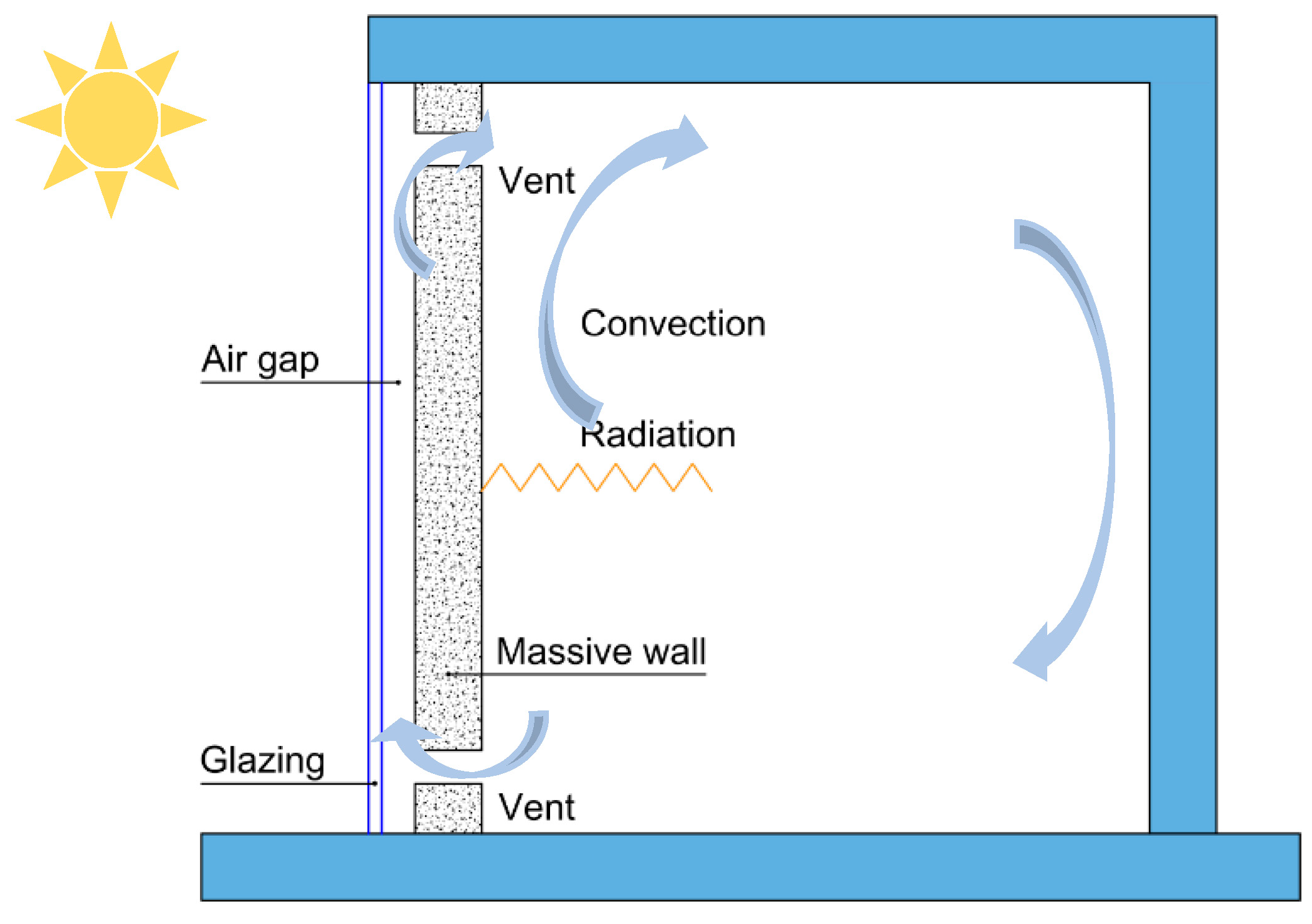
A typical Trombe wall structure consists of a massive thermal wall, with clear outer glazing and an air gap in between. A large thermal wall collects and stores incident solar energy. Such a typical Trombe wall consists of four main components: glass, air channel, thermal storage wall, and vents, if applicable (see Figure 1) [10].
The thermal storage wall shall be constructed from materials with a high thermal capacity, to enable solar radiation to be stored and accumulated for an extended period of time [11]. In order to achieve greater solar absorption, the wall surface is typically painted dark [12]. The glazing transmits light and produces a greenhouse effect within the air channel. The difference in air density between the warm air channel and the cold room then produces a space heating cycle [13]. During the day, sunlight passing through the glass is absorbed by the dark surface, stored in the wall, and slowly conducted inward through the massive wall [14]. High transmission glass optimizes solar gains for the massive wall [6]. The stored energy is then transferred to the interior of the structure for space heating or air circulation. The heating/cooling performance is dependent on the thermal conductivity of the massive wall, the airflow characteristics in the convective air cavity, and the room space itself (Figure 1) [15].
While Trombe wall systems offer substantial energy savings when the solar resource is available, in the conditions of insufficient solar radiation, these systems do not generate any heating (overcast, cloudy sky).
1.2. Performance-Improving Trombe Wall Modifications
More advanced Trombe wall applications may feature components to facilitate better solar energy utilization. As such, to enhance the performance of the traditional Trombe wall, numerous scholars have proposed a series of structural modifications to the original design (Figure 2) [2,17].
Trombe walls feature low thermal resistances and specific heat capacities. Moreover, heat transfer in Trombe walls occurs in an uncertain pattern. Solar intensity fluctuations render the amount of heat gained unpredictable [18]. The performance of Trombe walls can be significantly improved through various modifications, such as the use of PCMs (phase-change materials). By utilizing the high storage capacity of PCMs, the thermal resistance of a Trombe wall can be increased, to reduce heat dissipation and improve the control of solar radiation gain [19]).
Classical Trombe walls rely on sensible heat storage, yet due to the potential of PCMs to store a high amount of thermal energy per unit mass, the combination of PCMs with Trombe walls is an attractive concept for increasing the thermal storage of the conventional Trombe walls through latent heat storage [20,21].
Compared to a conventional Trombe wall, the PCM-Trombe wall demonstrates greater total energy savings. The optimal phase change temperature and thickness of a PCM depends significantly on the latitude and local shading. As a result of its high latent heat and thermal conductivity, hydrated salt exhibits fewer fluctuations in indoor temperature than paraffins [19].
PCM-Trombe walls demonstrate effective overheating prevention in the summer and satisfactory heating effects in the winter [19].
While Trombe wall systems have certain advantages, the system must be designed carefully, as this technology has a number of limitations.
The performance of a typical Trombe wall is dependent not only on its construction, but also on external factors such as the ambient temperature and the incident solar radiation. Consequently, it can contribute to the thermal comfort of a building, but it must be combined with other non-passive systems, that can provide heat when necessary [3,22].
Full-height Trombe walls completely block the sun’s direct rays from entering the building, necessitating an electrical lighting system in the room behind the wall even during the day, thereby increasing the building’s supplementary energy consumption [23].
Even if Trombe walls reduce the building’s energy consumption during the heating season, if they are poorly designed, they can act as additional cooling loads during the cooling season, consequently increasing the cooling energy requirements.
While Trombe wall systems are primarily used for winter heating, these systems can also be employed to reduce the summertime solar heating effect. However, rather than venting the solar energy-heated air, the energy can be used to heat domestic water. Moreover, the system can contribute to ventilation through the chimney effect [3,13].
As the prices of active and fossil energy sources continue to rise, Trombe wall technology, as a means for passive carbon-free energy generation and storage, is becoming increasingly appealing. Depending on the external climate and the desired level of indoor comfort, the Trombe wall may be combined with an alternative heating system [24]. Consequently, the Trombe wall is typically used as a supplementary system in cold-climate buildings, to save energy during the cold period of year. Incorporating a solar chimney into a Trombe wall can improve natural ventilation and reduce cooling loads during the cooling season [25].
2. Methodology
The amount and intensity of solar heat capture through a Trombe wall is determined by various factors, such as [26]:
- The effective surface area of the Trombe wall glazing layer, m2;
- The technical properties of the glass (material and thickness, transmission ratio, U-value, SHGC, etc.);
- The orientation of the wall in relation to the incident solar radiation.
However, not all of the incident solar radiation can be used entirely (due to several factors, such as diffusion, resistance, and losses), therefore, the solar heat gain through a Trombe wall glass layer can be calculated by the a following equation:
where:
Si—solar heat gains, W;
Sinc,n,i—daily solar radiation component on a vertically oriented surface, W;
Dn,i—shading coefficient;
SHGCn—solar heat gain coefficient.
From the scientific literature, it can be concluded that passive solar energy systems can be evaluated in a direct or indirect way. In the direct way, the methodology includes calculations that describe in detail the thermal performance of a given system element, including temperature graphs and CFD simulations [21].
In the indirect way, passive solar energy systems can be evaluated using various standards and regulations that are designed to evaluate the overall energy efficiency of a building. In this case, the efficiency of the system is expressed as energy savings from the total energy consumption of the building, or as total solar heat gains [27,28].
The simplest method is to calculate the heat flow using the Trombe wall heat transfer coefficient U, and the minimum outdoor air temperature, according to the formula:
In this case, the calculated heat flow characterizes the heat loss through the Trombe wall, without taking into account the heat capacity of the structure and assuming that no solar radiation is available. For a more accurate calculation of the heat flow, the hourly outdoor air temperature, or the so-called sol-air temperature, can be used [29,30].
Tsol-air is the assumed outdoor air temperature, which, in the absence of direct solar radiation and no air movement, produces the same heat transfer in the building as is caused by the interaction of all existing atmospheric conditions, which is calculated by the following Equation (3):
which in turn produces (4):
It should be noted that when calculating the heat flows according to Equation (4), the characteristics of the glass layer of the Trombe wall are not taken into account.
By including the solar energy transmission coefficient τ, and the thermal transmittance coefficient of the glass, the corrected sol-air temperature can be calculated by Equation (5):
To perform year-long energy output measurements in a real operational setting, a Trombe wall structure was designed, and integrated onto a factory wall’s southern-facing surface.
The factory building is a 1000 m2 sheet metal hangar, that has been converted into a timber-frame structure modular house component (walls, floors, roof, windows) production and assembly factory. On average, 15 factory workers are present at the factory on a regular day.
The factory features a poorly insulated external envelope, consisting of corrugated sheet metal panels attached on top of concrete columns and beams.
Therefore, the indoor conditions strongly depend on the outdoor conditions, suggesting that in the cold season, the indoor temperature may drop below that of the minimum threshold stipulated in Cab. Reg. No. 359 ‘Labour Protection Requirements in Workplaces’ (see Table 1).
A category III work environment describes heavy work (for example, permanent lifting and movement of weights), which matches the factory’s employees’ work type, and therefore, in the cold season (October–April) the minimum workplace temperature should not fall below 13.0 °C.
To maintain the desired indoor temperature setting in the cold season, electrical heaters were usually employed, however, due to a rapid increase in the cost of electricity, and the general need of more sustainable forms of space heating generation, a Trombe wall system was integrated onto the factory’s wall.
The Trombe wall’s characteristics are listed in Table 2.
The Trombe wall consisted of timber wood framing and polycarbonate sheets, used as a transparent outer surface to transmit incident solar radiation. The dark corrugated metal sheet factory wall served as a backwall to absorb the incident solar radiation (no thermal mass).
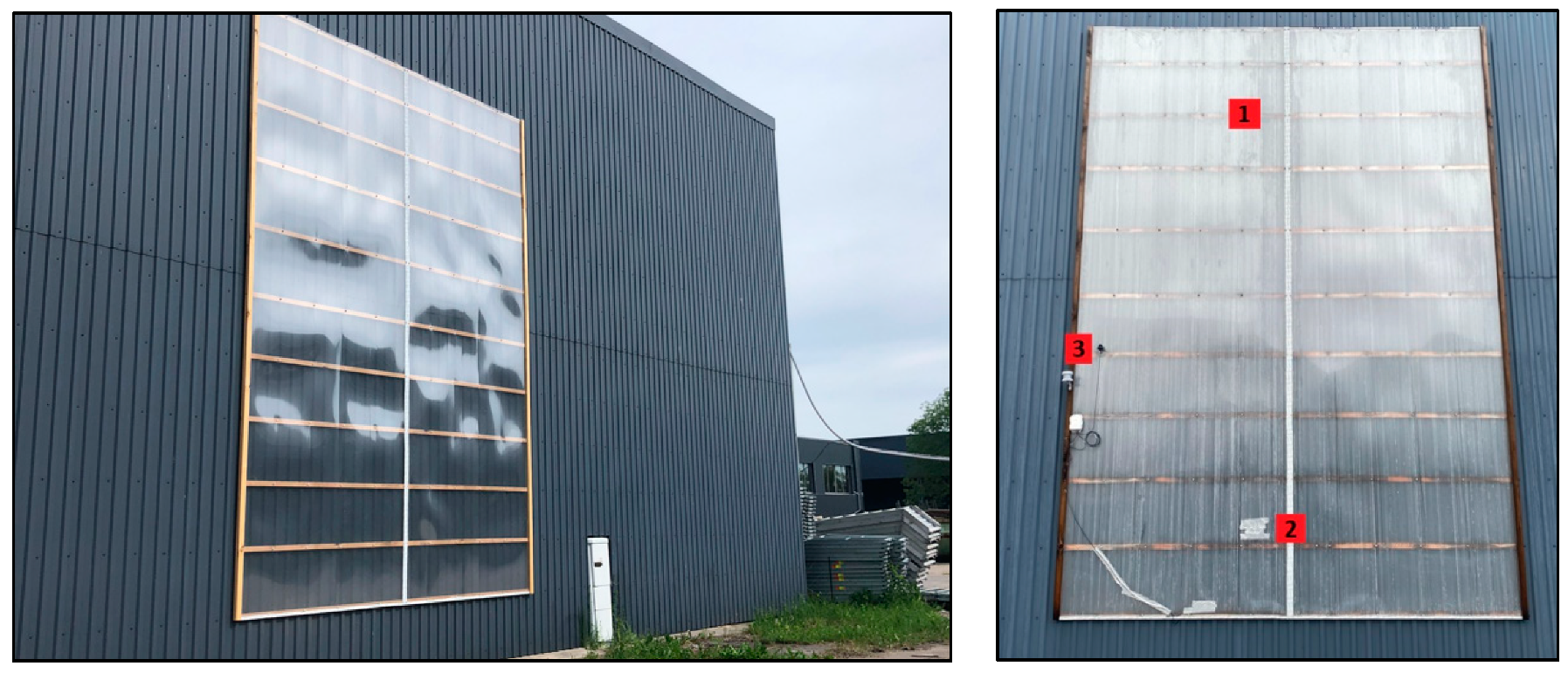
The installed Trombe wall system on the factory building’s facade is shown in Figure 3.
The labelled points in Figure 3 indicate the sensors’ positions: (1) temperature sensor at 5 m height inside the TW; (2) temperature sensor at 1.5 m height inside the TW; (3) solar radiation sensor.
At 5 m above the ground, a vent and a supply duct fan were installed to discharge the accumulated thermal air mass into the factory at a constant discharge flowrate of 200 m3/h, to ensure air movement across the wall structure.
A 100 mm air channel was integrated inside the Trombe wall structure to house the duct fan. A flexible air duct was attached to the fan to direct the heated air mass to the working area inside the factory. The air duct was insulated with 30 mm mineral wool insulation to prevent a drop in the supply air temperature.
The following continuous temperature measurements were carried out at 10-min intervals:
- outdoor temperature;
- indoor temperature (near the working area);
- temperature inside the Trombe wall at 1.5 m height;
- temperature inside the Trombe wall at 5 m height;
- supply air temperature (after the duct fan).
The incident solar radiation (W/m2) onto the Trombe wall structure was also monitored.
3. Results
The presented experimental Trombe wall prototype, and the acquired results, show that during sunny summer and early fall days, the temperature inside the wall structure may increase up to 80 to 85 °C (without heat discharge, when the supply fan is OFF). This indicates that there is a high potential of employing such systems as a secondary heating source in residential (and possibly industrial) applications, however, this aspect has to be tested in a real operational setting, with continuous or intermittent discharge of the accumulated heat energy to the end-user.
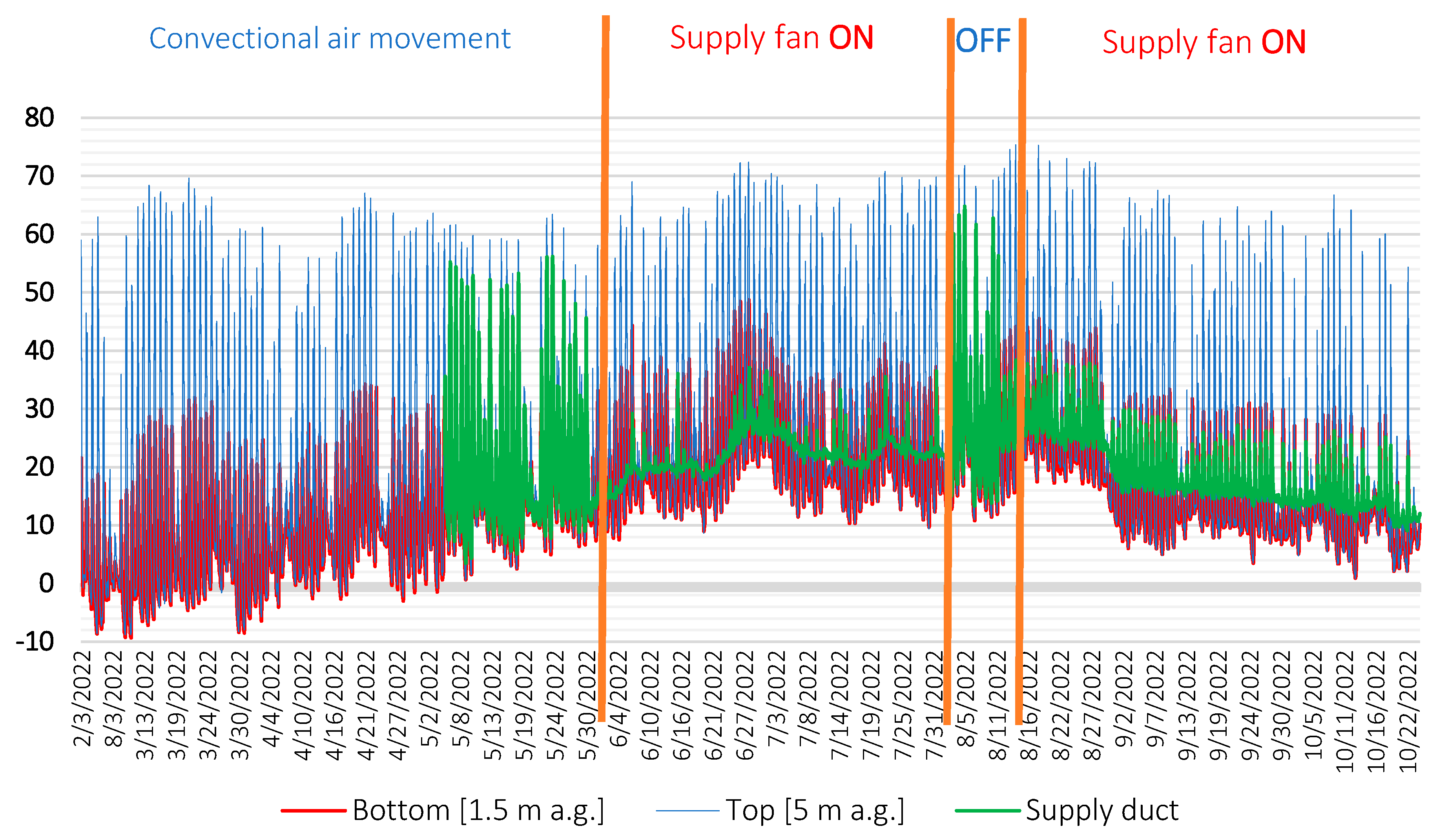
The temperature measurements of the Trombe wall system installed on the factory building suggested a favorable temperature gradient development between the bottom section (1.5 m above ground) and the top section (5 m above ground).
At is seen in Figure 4, when the supply duct fan was ON, the supply temperature (delivered temperature into the factory) ranged between 10 to 20 °C, depending on the outdoor conditions, regardless of the air mass temperature at the top of the Trombe wall (5 m).
This suggests that a good mixing is ensured when the air mass inside the Trombe wall is introduced into the factory building by a fan operation. As the air mass does not have sufficient buffer time to accumulate thermal energy when the fan is in constant operation, it passes through the air gap of the Trombe wall at a rather high velocity, insufficient to accumulate a substantial amount of heat energy (kJ) to increase its temperature beyond 10 °C above the bottom section’s temperature reading.
On the other hand, when the supply fan is OFF, the supply temperature is equal to the temperature reading at the top of the wall, which supports the proposal that a uniform temperature gradient can be observed inside the Trombe wall structure, with a substantially lower temperature reading at the bottom section, and a far higher temperature reading at the top section of the wall.
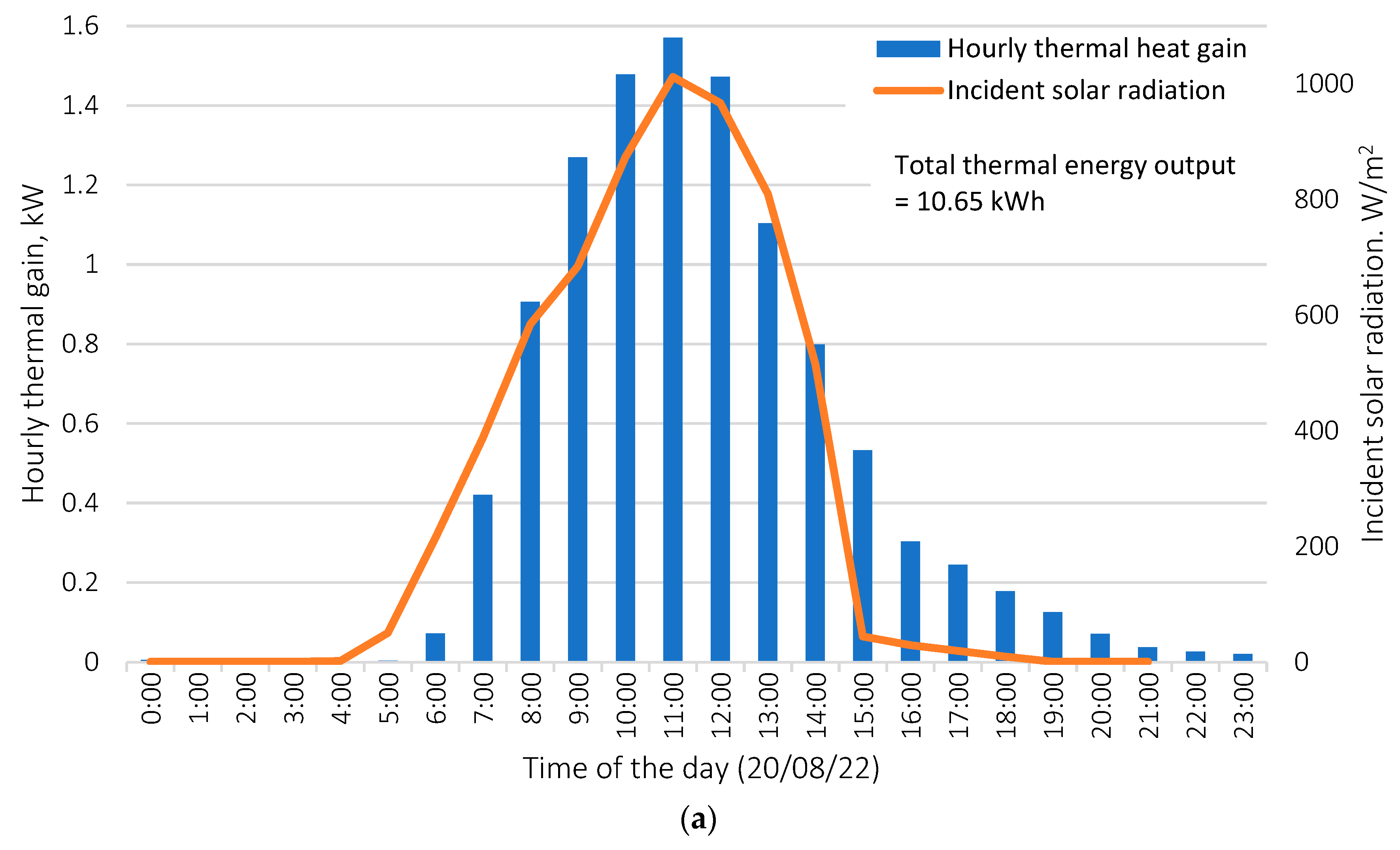
The heat gain output’s dependence on the incident solar radiation is shown in Figure 5.
Figure 5a shows the hourly thermal energy gain (kWh) of a Trombe wall operating on a sunny day, with a total energy output throughout the day of 10.65 kWh.
Figure 5b shows the hourly thermal energy gain (kWh) of a Trombe wall on a cloudy/overcast day, with a total energy output throughout the day of 0.82 kWh.
Figure 5a,b show the significant difference between the Trombe wall’s performance and high dependence on the incident solar radiation.
Table 3 compiles the monthly thermal energy yield throughout the months of June to October. As is seen, the current system generated 288 kWh of energy in July, which is the sunniest month in Latvia, while in October, which features predominantly overcast and rainy weather, the system generated 120 kWh of energy.
When translated into an energy yield per surface area of the wall (kWh/m2), and volume of the wall (kWh/m3), it gives a better insight into the energy yield produced by a unit of the wall structure, depending on its effective surface area and the air gap volume (non-variable parameters), and on the incident solar radiation (variable parameter).
4. Discussion
The obtained results from the experimental Trombe wall structure contribute to the existing studies of Trombe walls’ performances, and their potential for use in moderate/cold climate regions.
As mentioned previously, the current Trombe wall structure is installed on the factory building’s wall facing east, which suggests that the same Trombe wall structure would generate at least 30% higher output had it been installed on the southern wall of the factory building.
This, however, may present additional challenges, such as using different, i.e., more temperature and UV resistant, materials to avoid material damage (or self-ignition) due to overheating, as the temperature inside the air channel may rise up to 100–120 °C on hot summer days [21,31]. As the southern facade is exposed to the solar radiation for a prolonged period of time, perhaps, polycarbonate may not even be a feasible option as the transparent surface, and thus more rigid and weather-resistant materials, such as glass, may have to be used [11,32].
However, that deviates from the fundamental course of the current study.
It is important to note that the current structure was assembled using readily available (non-tailor made, retail-prone), low-cost, and lightweight materials, resulting in an easy and fast assembly. Moreover, the current structure was assembled onto the factory’s wall with very little structural intervention, as it requires only fastening and attaching the timber frame onto the factory’s metal sheeting, with the subsequent attachment of the polycarbonate sheets onto the timber frame. As such, the examined Trombe wall is deemed to be a lightweight and low-cost structure, that does not require special skills and industrial equipment for its installation, apart from an industrial lift.
The only mechanical component of the Trombe wall system is a fan, that facilitates the air intake and circulation throughout the wall, as well as discharge into the premises—in this case, into the factory building.
The fan’s energy consumption at 220 m3/h is 55 W, which comes out to 39.6 kWh of total energy consumption (if in full operation mode) for a given month. However, if equipped with an electric interval timer, the fan can be switched off during the night, allowing for less power consumption, and thus, a higher Trombe wall thermal energy performance ratio in relation to the power consumed by the fan’s operation [6,31].
Provided that factory buildings are usually spacious and feature high ceilings, the air mass should be diverted or delivered directly into the working zone via local supply ductwork. This will facilitate the conservation and targeting of the generated thermal energy directly into the working area, instead of heating up the nearby zones or the upper part of the factory building. Furthermore, the supply duct should be well insulated, to avoid heat loss, as the heated air cools down as it passes through the duct to the dedicated working zone (Figure 6).
A Trombe wall system has the potential to reduce or partly offset the heating needs in industrial applications, as industrial premises such as factories, are unclassified buildings and normally do not require high indoor comfort.
As such, these systems may also be used to preheat the primary air supply in cold (and moderate) times of the year before entering heat recovery units in industrial/commercial buildings equipped with mechanical ventilation systems [32].
Even a slight temperature increase above the outdoor temperature before the heat recovery unit may result in significant savings, when taken across the entire year.
As for during warm and hot times of the year, a Trombe wall system is very easily disabled, by leaving it idle (turning the fan off), and by opening the outdoor vents while shutting the indoor vents (if applicable) to let the outdoor air simply circulate through it with no heating effect on the corresponding building.
The examined factory building features a high ceiling, low air tightness, and heavy concrete structure, that naturally contributes to keeping the premises cool even in the warmer months of the year.
Therefore, the Trombe wall system may contribute to a greater indoor comfort even in the warm times of the year, by delivering warm air into the working zone (Figure 7).
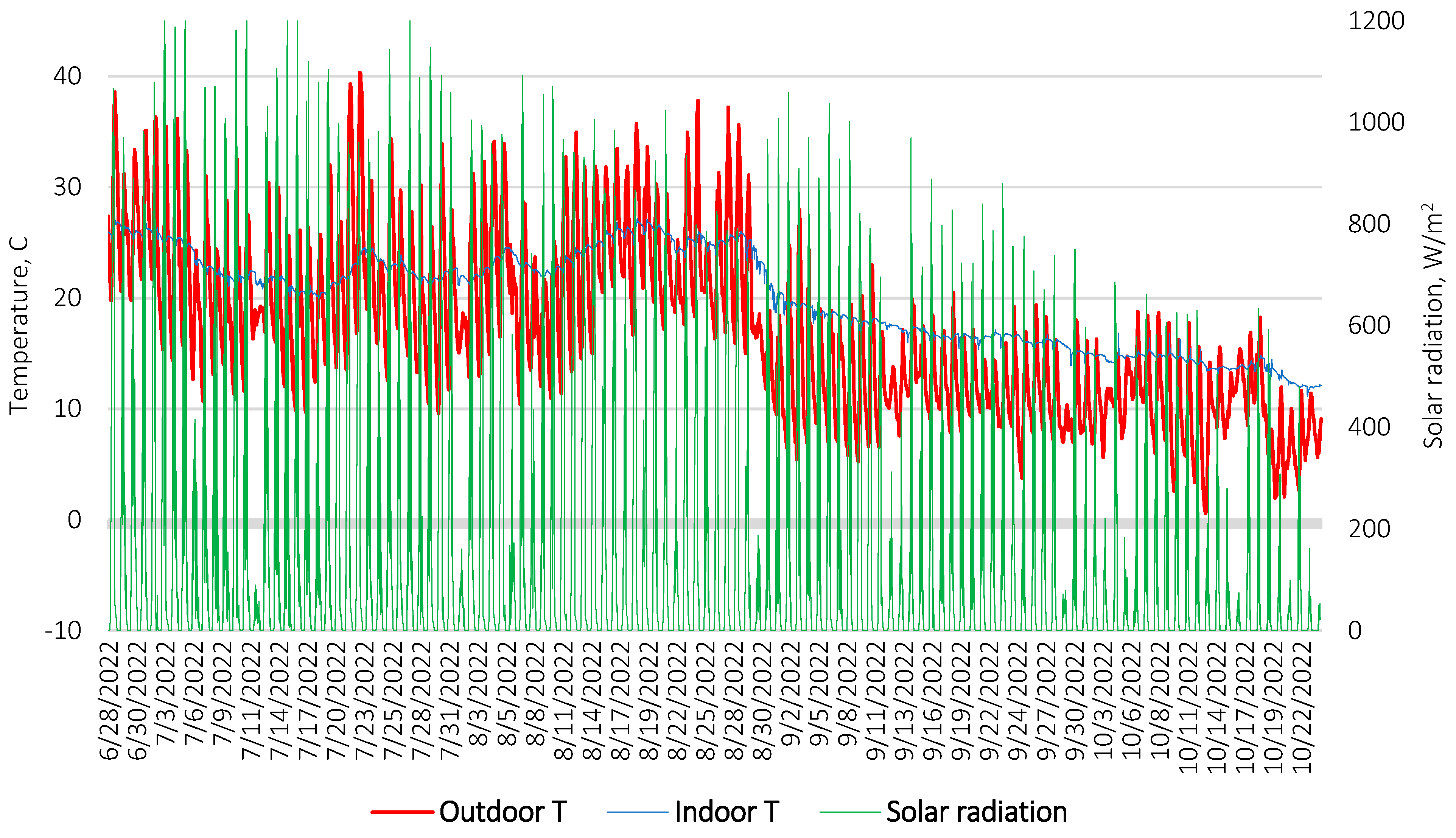
The indoor temperature inside the factory’s working area varies between 20 and 25 °C between June and September, and then it is gradually and steadily dropping throughout the months of September and October (20 °C to 13 °C). This is caused by a steady drop in the incident solar radiation with the advent of cooler and wetter air masses around mid-September (Figure 7).
Trombe walls have not been studied sufficiently in moderate and cold climatic conditions, with variable precipitation and a few hours of sunshine, so it is not possible to predict the impact of icing on the importance of the surface, and the albedo effect of the structure in winter conditions.
5. Conclusions
Trombe Wall technology offers a number of advantages as a passive solar heating system: being a renewable and clean energy source, being a low-budget and maintenance-free solution, as well as, both heating and cooling of the premises with proper design modifications.
However, this technology is entirely dependent on the intensity of the incident solar radiation and, therefore, might present a number of limitations, such as intermittency of heat energy production. These systems are also difficult to control, and in sunny regions there is a risk of structural damage due to overheating if a Trombe wall system is designed or installed improperly.
The use of passive solar energy systems provides a heat source that is difficult to predict and variable over time. Such systems cannot provide an independent or stable amount of heat energy and therefore should not be used as a primary source of heat energy. The design of a Trombe wall is a complex process, in which the technical solution of each structure must be applied to the individual geographical and climatic conditions of the building.
Trombe walls provide heat accumulation in the wall, and such systems have a high inertia, which can interfere with the desired indoor comfort settings. A more reasonable application of these walls is in the industrial or unclassified settings, where occupants do not require a high level of indoor comfort or stable indoor temperature conditions (unless supplemented with another, i.e., primary, heating source).
The analyzed Trombe wall system, on the factory building, had a monthly energy yield in the range of 120 to 290 kWh (June–October), suggesting that the system has a reasonable potential to reduce or partly offset thermal energy consumption for space heating needs. A southern facing Trombe wall structure in the same conditions and application may produce around a 30% higher thermal energy yield.
Moreover, if scaled up and designed correctly, the system may produce a reasonable thermal energy output to substantially reduce an industrial plant’s or factory’s heating energy bills with a relatively low investment.
Trombe wall systems may be applicable as a secondary heating source in cold climate regions such as northern European regions (Baltic States, Scandinavian region, etc.), however, a larger scale and open cycle system has to be tested throughout the meaningful timeframe (fall and winter seasons).
On top of the aforementioned limitations that were considered within the framework of this report, it is suggested that forced air circulation options are reviewed to facilitate (a) heat transfer rate, (b) air discharge rate, and (c) thermal comfort on the receiving end (at the end-user side), as well as reviewing potential air treatment (filtering) options to avoid pollution and contamination build-up in the wall structure, and thus, in the recirculated air mass.
Author Contributions
Conceptualization, A.P. and A.B.; methodology, A.P. and A.B.; resources, A.P., validation—A.B.; writing—original draft preparation, A.P.; revision—A.B. and D.B.; visualization, A.P. and A.B.; supervision, A.B. All authors have read and agreed to the published version of the manuscript.
Funding
This research is supported by European Regional Development Fund project “A new concept for low-energy eco-friendly house”, Grant Agreement No 1.1.1.1/19/A/017.
Data Availability Statement
The data presented in this study are available on request from the corresponding author.
Conflicts of Interest
The authors declare no conflict of interest.
References
- Göksal Özbalta, T.; Kartal, S. Heat Gain through Trombe Wall Using Solar Energy in a Cold Region of Turkey. Sci. Res. Essays 2010, 5, 2768–2778. [Google Scholar]
- Wang, D.; Hu, L.; Du, H.; Liu, Y.; Huang, J.; Xu, Y.; Liu, J. Classification, Experimental Assessment, Modeling Methods and Evaluation Metrics of Trombe Walls. Renew. Sustain. Energy Rev. 2020, 124, 109772. [Google Scholar] [CrossRef]
- Wu, S.-Y.; Wu, L.-F.; Xiao, L. Effects of Aspect Ratio and Inlet Wind Velocity on Thermal Characteristics of Trombe Wall Channel under Different Ventilation Strategies: An Indoor Experiment. Exp. Therm. Fluid Sci. 2023, 141, 110800. [Google Scholar] [CrossRef]
- Borodinecs, A.; Zemitis, J.; Prozuments, A. Passive Use of Solar Energy in Double Skin Facades for Reduction of Cooling Loads. 2012. Available online: https://alephfiles.rtu.lv/TUA01/000039278_e.pdf (accessed on 8 February 2023).
- Hu, Z.; He, W.; Ji, J.; Zhang, S. A Review on the Application of Trombe Wall System in Buildings. Renew. Sustain. Energy Rev. 2017, 70, 976–987. [Google Scholar] [CrossRef]
- Szyszka, J.; Bevilacqua, P.; Bruno, R. An Innovative Trombe Wall for Winter Use: The Thermo-Diode Trombe Wall. Energies 2020, 13, 2188. [Google Scholar] [CrossRef]
- Charqui, Z.; Boukendil, M.; el Moutaouakil, L.; Hidki, R.; Zrikem, Z.; Abdelbaki, A. Simulation and Optimization of the Thermal Behavior of a Trombe Wall under Unsteady Conditions. Mater. Today Proc. 2022. [Google Scholar] [CrossRef]
- Charqui, Z.; el Moutaouakil, L.; Boukendil, M.; Hidki, R.; Zrikem, Z.; Abdelbaki, A. Numerical Simulation of Turbulent Coupled Heat Transfer in a Trombe Wall Subjected to Periodic Thermal Excitations. Energy Build 2023, 278, 112631. [Google Scholar] [CrossRef]
- Matasane, C.; Kahn, M.-T. Solar Energy Assessment, Estimation, and Modelling Using Climate Data and Local Environmental Conditions. Adv. Sci. Technol. Eng. Syst. J. 2022, 7, 103–111. [Google Scholar] [CrossRef]
- Ji, E.; Yi, H.; He, W.; Pei, G. PV-Trombe Wall Design for Buildings in Composite Climates. J. Sol. Energy Eng. Trans. ASME 2007, 129, 431–437. [Google Scholar] [CrossRef]
- Facelli Sanchez, P.; Mercado Hancco, L. Trombe Walls with Porous Medium Insertion and Their Influence on Thermal Comfort in Flats in Cusco, Peru. Energy Built Environ. 2022. [Google Scholar] [CrossRef]
- de Rubeis, T.; Evangelisti, L.; Guattari, C.; de Berardinis, P.; Asdrubali, F.; Ambrosini, D. On the Influence of Environmental Boundary Conditions on Surface Thermal Resistance of Walls: Experimental Evaluation through a Guarded Hot Box. Case Stud. Therm. Eng. 2022, 34, 101915. [Google Scholar] [CrossRef]
- Jaber, S.; Ajib, S. Optimum Design of Trombe Wall System in Mediterranean Region. Sol. Energy 2011, 85, 1891–1898. [Google Scholar] [CrossRef]
- Szyszka, J. From Direct Solar Gain to Trombe Wall: An Overview on Past, Present and Future Developments. Energies 2022, 15, 8956. [Google Scholar] [CrossRef]
- Mokni, A.; Lashin, A.; Ammar, M.; Mhiri, H. Thermal Analysis of a Trombe Wall in Various Climatic Conditions: An Experimental Study. Sol. Energy 2022, 243, 247–263. [Google Scholar] [CrossRef]
- Grazuleviciute-Vileniske, I.; Seduikyte, L.; Teixeira-Gomes, A.; Mendes, A.; Borodinecs, A.; Buzinskaite, D. Aging, Living Environment, and Sustainability: What Should Be Taken into Account? Sustainability 2020, 12, 1853. [Google Scholar] [CrossRef]
- Szyszka, J.; Bevilaqua, P.; Bruno, R. A Statistical Analysis of an Innovative Concept of Trombe Wall by Experimental Tests. J. Build. Eng. 2022, 62, 105382. [Google Scholar] [CrossRef]
- Akaf, H.R.; Kohansal, M.E.; Moshari, S.; Gholami, J. A Novel Decision-Making Method for the Prioritization of Passive Heating Systems Use; Case Study: Tehran. J. Build. Eng. 2019, 26, 100865. [Google Scholar] [CrossRef]
- Shadram, F.; Mukkavaara, J. Exploring the Effects of Several Energy Efficiency Measures on the Embodied/Operational Energy Trade-off: A Case Study of Swedish Residential Buildings. Energy Build 2019, 183, 283–296. [Google Scholar] [CrossRef]
- Sun, X.; Gou, Z.; Lau, S.S.Y. Cost-Effectiveness of Active and Passive Design Strategies for Existing Building Retrofits in Tropical Climate: Case Study of a Zero Energy Building. J. Clean. Prod. 2018, 183, 35–45. [Google Scholar] [CrossRef]
- Zhu, Y.; Zhang, T.; Ma, Q.; Fukuda, H. Thermal Performance and Optimizing of Composite Trombe Wall with Temperature-Controlled DC Fan in Winter. Sustainability 2022, 14, 3080. [Google Scholar] [CrossRef]
- Sheikholeslami, M.; Al-Hussein, H.R.A. Modification of Heat Storage System Involving Trombe Wall in Existence of Paraffin Enhanced with Nanoparticles. J. Energy Storage 2023, 58, 106419. [Google Scholar] [CrossRef]
- Li, J.; Zhang, Y.; Zhu, Z.; Zhu, J.; Luo, J.; Peng, F.; Sun, X. Thermal Comfort in a Building with Trombe Wall Integrated with Phase Change Materials in Hot Summer and Cold Winter Region without Air Conditioning. Energy Built Environ. 2022. [Google Scholar] [CrossRef]
- Almihat, M.; Kahn, M.-T.; Abo-Al-Ez, K.; Almaktoof, A. Energy and Sustainable Development in Smart Cities: An Overview. Smart Cities 2022, 5, 1389–1408. [Google Scholar] [CrossRef]
- Mohamad, A.; Taler, J.; Ocłoń, P. Trombe Wall Utilization for Cold and Hot Climate Conditions. Energies 2019, 12, 285. [Google Scholar] [CrossRef]
- Fokaides, P.A.; Apanaviciene, R.; Černeckiene, J.; Jurelionis, A.; Klumbyte, E.; Kriauciunaite-Neklejonoviene, V.; Pupeikis, D.; Rekus, D.; Sadauskiene, J.; Seduikyte, L.; et al. Research Challenges and Advancements in the Field of Sustainable Energy Technologies in the Built Environment. Sustainability 2020, 12, 8417. [Google Scholar] [CrossRef]
- Harkouss, F.; Fardoun, F.; Biwole, P.H. Passive Design Optimization of Low Energy Buildings in Different Climates. Energy 2018, 165, 591–613. [Google Scholar] [CrossRef]
- Lohmann, V.; Santos, P. Trombe Wall Thermal Behavior and Energy Efficiency of a Light Steel Frame Compartment: Experimental and Numerical Assessments. Energies 2020, 13, 2744. [Google Scholar] [CrossRef]
- Abdullah, A.A.; Atallah, F.S.; Algburi, S.; Ahmed, O.K. Impact of a Reflective Mirrors on Photovoltaic/Trombe Wall Performance: Experimental Assessment. Results Eng. 2022, 16, 100706. [Google Scholar] [CrossRef]
- Omara, A.A.M.; Abuelnuor, A.A.A. Trombe Walls with Phase Change Materials: A Review. Energy Storage 2020, 2, e123. [Google Scholar] [CrossRef]
- Tian, Z.; Zhang, X.; Jin, X.; Zhou, X.; Si, B.; Shi, X. Towards Adoption of Building Energy Simulation and Optimization for Passive Building Design: A Survey and a Review. Energy Build 2018, 158, 1306–1316. [Google Scholar] [CrossRef]
- Asdrubali, F.; Baldinelli, G.; Bianchi, F.; Cornicchia, M. Experimental Performance Analyses of a Heat Recovery System for Mechanical Ventilation in Buildings. Energy Procedia 2015, 82, 465–471. [Google Scholar] [CrossRef]
Figure 1.
Operation principle of a classic Trombe wall, and energy gain. (adopted from [16]).
Figure 1.
Operation principle of a classic Trombe wall, and energy gain. (adopted from [16]).

Figure 2.
Various types and modifications of Trombe wall technology [3].
Figure 2.
Various types and modifications of Trombe wall technology [3].

Figure 3.
A Trombe wall structure installed onto a factory building in Kalnciems, Latvia.

Figure 4.
Temperature measurements at the top and bottom of the Trombe wall installed onto a factory building.
Figure 4.
Temperature measurements at the top and bottom of the Trombe wall installed onto a factory building.

Figure 5.
(a). Hourly thermal energy production (kWh) on a clear day (peak incident solar radiation > 1000 kWh/m2). (b). Hourly thermal energy production (kWh) on a cloudy day (peak incident solar radiation < 200 kWh/m2).
Figure 5.
(a). Hourly thermal energy production (kWh) on a clear day (peak incident solar radiation > 1000 kWh/m2). (b). Hourly thermal energy production (kWh) on a cloudy day (peak incident solar radiation < 200 kWh/m2).


Figure 6.
Optimal Trombe wall system layout and configuration for the examined case of a factory building.
Figure 6.
Optimal Trombe wall system layout and configuration for the examined case of a factory building.

Figure 7.
Incident solar radiation, outdoor and indoor temperature.


Table 1.
Requirements for the Microclimate of Work Premises Depending on Physical Load (Cab. Reg. No. 359 ‘Labour Protection Requirements in Workplaces’).
Table 1.
Requirements for the Microclimate of Work Premises Depending on Physical Load (Cab. Reg. No. 359 ‘Labour Protection Requirements in Workplaces’).
| Time of the Year | Work Category | Air Temperature (°C) |
|---|---|---|
| Cold time of the year (average air temperature outside work premises +10 °C or lower) | I | 19.0–25.0 |
| II | 16.0–23.0 | |
| III | 13.0–21.0 |
Table 2.
Trombe wall structure’s profile.
| Trombe Wall—Real-Operating Setup | |
|---|---|
| Location | Kalnciems, Latvia |
| Position | Fully vertical |
| Orientation | Due east |
| Operation | Passive solar heat transmission; fan-enforced air circulation ~200 m3/h |
| Position towards outdoor weather conditions/elements | Fully exposed |
| Height, mm | 5400 |
| Width, mm | 4000 |
| Surface area, m2 | 21.6 |
| Depth, mm | 70 (50 + 40/0) |
| Volume of air gap, m3 | 0.69 |
| Measurement, unit | Temperature, °C |
| No. of measurement points | 4 |
| Backwall material | Sheet metal plates |
| Glazing material | Polycarbonate sheets |
| Frame material | Timber |
| Backwall material | Corrugated, galvanized and painted sheet metal |
| Measurement timeframe | Spring 2022—Fall 2022 |
Table 3.
Thermal energy yield (June—October 2022).
| Monthly Thermal Energy Yield, kWh | |||
|---|---|---|---|
| Energy Yield | |||
| Month | kWh | kWh/m2 | kWh/m3 |
| June | 233.79 | 10.82 | 338.24 |
| July | 288.40 | 13.35 | 417.25 |
| August | 239.06 | 11.07 | 345.86 |
| September | 207.13 | 9.59 | 299.67 |
| October | 119.66 | 5.54 | 173.12 |
Disclaimer/Publisher’s Note: The statements, opinions and data contained in all publications are solely those of the individual author(s) and contributor(s) and not of MDPI and/or the editor(s). MDPI and/or the editor(s) disclaim responsibility for any injury to people or property resulting from any ideas, methods, instructions or products referred to in the content. |
© 2023 by the authors. Licensee MDPI, Basel, Switzerland. This article is an open access article distributed under the terms and conditions of the Creative Commons Attribution (CC BY) license (https://creativecommons.org/licenses/by/4.0/).
Share and Cite
MDPI and ACS Style
Prozuments, A.; Borodinecs, A.; Bajare, D. Trombe Wall System’s Thermal Energy Output Analysis at a Factory Building. Energies 2023, 16, 1887. https://doi.org/10.3390/en16041887
AMA Style
Prozuments A, Borodinecs A, Bajare D. Trombe Wall System’s Thermal Energy Output Analysis at a Factory Building. Energies. 2023; 16(4):1887. https://doi.org/10.3390/en16041887
Chicago/Turabian StyleProzuments, Aleksejs, Anatolijs Borodinecs, and Diana Bajare. 2023. "Trombe Wall System’s Thermal Energy Output Analysis at a Factory Building" Energies 16, no. 4: 1887. https://doi.org/10.3390/en16041887
Note that from the first issue of 2016, this journal uses article numbers instead of page numbers. See further details here.