
From Direct Solar Gain to Trombe Wall: An Overview on Past, Present and Future Developments


Faculty of Civil and Environmental Engineering and Architecture, Rzeszow University of Technology, 35-959 Rzeszów, Poland
Energies 2022, 15(23), 8956; https://doi.org/10.3390/en15238956
Submission received: 10 October 2022
/
Revised: 8 November 2022
/
Accepted: 18 November 2022
/
Published: 27 November 2022
(This article belongs to the Section G: Energy and Buildings)
Abstract
:The energy crisis, the risk of interruptions or irregular supplies of conventional energy carriers, and the need to protect the environment stimulate the search for new solutions to improve the heat balance of buildings with the use of solar energy. In this paper, direct and indirect solar gain systems integrated with the building envelope are discussed. In the context of the identified operational problems, the evolution of the classic Trombe wall was shown in the period 1967–2022. Modifications to the windows and Trombe wall proposed in the reviewed works can significantly reduce the risk of an insufficient supply of heat in the winter season. This review also indicates the impact of climate conditions on the decision-making process involved in the selection of the Trombe wall design with respect to energy–effects optimization. The insufficient thermal insulating capacity of Trombe walls has been diagnosed as the reason why they do not enjoy much popularity in cold and moderate climates. As the main directions of development of solar gains systems, the search for solutions that maximize solar gains while ensuring high standards of thermal insulation and the implementation of intelligent technologies were indicated.
1. Introduction
In the current geopolitical situation and in the face of the growing threat of a deepening energy crisis, the priority is to look for new solutions to reduce the demand for conventional energy, especially in the construction sector, which is responsible for approximately 40% of global energy consumption and over 36% of carbon dioxide emissions [1,2,3]. The activities aimed at meeting this goal, which are limited to legislation that enforces more stringent requirements concerning the thermal resistance of buildings’ envelope elements or systems of heat recovery, are far from satisfactory. Design and execution standards should include the necessity of the use of energy from renewable sources, the implementation of innovative solutions that combine favorable economic effects with provisions for healthcare and the comfort of inhabitants while reducing the unfavorable impact of buildings on the natural environment. Considerable reserves in this respect lie in the elements of the buildings’ envelopes. We are witnessing their evolution from traditional and monofunctional to multifunctional or even interactive based on novel materials with improved properties and the utilization of cutting-edge technologies that enable a response to changing environmental conditions. Elements of buildings’ envelopes, to which this paper is devoted, have a special feature: the ability to improve thermal balance owing to the photothermal conversion of solar radiation energy.
The main aim of the review is to evaluate the potential of selected solutions for solar gain systems with regard to their applicability in selected climatic conditions and an analysis of possible hazards related to their use. The criteria analyzed for the classification of the solutions were as follows: their belonging to direct or indirect systems, the process of heat exchange with the building, the thermal insulation capacity, and additional functions. This review covers the leading and most-interesting modifications of solutions researched in the period of 1973–2022. The quantitative indices of efficiency quoted by the authors are not universal in character, as they result from case studies. Therefore, the analysis and evaluation of the applicability of the discussed solutions were based primarily on qualitative criteria.
2. Overview and Discussion
Based on the criterion of the storage, distribution, and discharge time of stored heat, passive solar gain solutions can be divided into direct and indirect solar gain systems.
2.1. Direct Solar Gain Systems
Direct solar gain is the most basic form of solar gain of heat. The solar radiation penetrating through the glazing is absorbed by the thermal mass built into the floor and walls, where it undergoes photothermal conversion (Figure 1). Its quantity is determined by the structural features of the building, the orientation of the glazing relative to the cardinal directions or topography, and vegetation and building elements that may periodically shade the glazing.
During the design of direct solar gain systems, it is sufficient to choose the aforementioned elements, the thermal mass of the building, and the heat-gain diversification so as to guarantee maximum heat collection during solar radiation while minimizing the risk of exceeding the target temperature level of interior air.
Among the basic structural features of the building that affect direct solar gain, Jäger [4] includes a south-facing at least double-glazed window of considerable surface and a window night insulation system as protection against excessive heat loss. However, glazings of the considerable area may result in an uncontrolled increase of temperature in rooms. The selection of adequate thermophysical parameters for the glazing according to the function of the room and its orientation relative to the cardinal directions becomes a key factor. The reason why it is difficult to select a universal glazing that yields the most favorable energy balance is that the solar energy transmittance and thermal resistance parameters are significantly divergent. Insulation can be improved by, inter alia, the use of advanced glazed units containing E-low or electrochromic coatings [5,6,7], vacuum glazing [8,9,10], as well as noble gases in the spaces between the glazed units. These methods may considerably reduce the heat transfer coefficient of glazing, Ug (with argon by −22.2%, with krypton by −33.3%, and with xenon −41.1%, respectively), compared with the Ug of glazed units filled only with air [11]. In their experiments on revolving glass panes, Saleh et al. [12] found that the azimuthal rotation of glazing, while maintaining the same original direction of the wall, is an effective means of ameliorating the solar heat gain to the space (alleviating or augmenting the heat gain for cooling or heating purposes, respectively).
When full transparency of glazing is not required, the spaces between the glazed units can be filled with a transparent insulating material (TIM) [13] which has solar transmittance capacity: e.g., capillary polycarbonate or glazed units filled with granulated aerogel [14,15,16,17] or a cellular filling reducing the proportion of convection in heat exchange (Figure 2).
In cases of insufficient solar radiation or at night, thermal insulation can be improved by using various types of movable insulation: blinds, blinds with a reflective coating, shutters, and roller blinds [18]. For years, the idea of dynamic insulation has been developed. For example, in the concept described in [19], at night or in the event of insufficient solar radiation, the spaces between the boards are filled under pressure with expanded polystyrene granulate. In addition to increasing the thermal resistance of the wall, analogous solutions can perfectly prevent the building from overheating in the summer and wasting energy on cooling [20,21]. Casini [22] assessed the effect of shading using dynamic windows. Sbar et al. [23] performed a simulation for electrochromic windows in three American cities—Washington, Minnesota, and Phoenix and found energy savings at the level of 10%, 20%, and 4%, respectively. Tests on the prototype of switchable insulated shading (SIS) indicated differences in annual energy consumption by HVAC ranging from 8.2 in cold climates to over 11% in warm and hot climates [24]. Bellia et al. [25] demonstrated savings in cooling energy at a level of 20% in the Palermo climate, 15% in Rome, and 8% in Milan as a result of the application of shading elements in office buildings. Yao [26] presented a study on the impact of dynamic sun blinds on energy and comfort and showed that the energy demand in a building can be reduced by 30.87% using external movable roller blinds for the city of Ningbo in China.
In summer, when required, the glazed part of the elevation can also be shaded by the building’s overhanging elements [27], for example, eaves, jutties, balconies, or loggias.
Direct solar gains are proportional to the windows’ area. However, if they are too large, they can cause periodic temperature fluctuations that cause room overheating and compromise the comfort of using them [28,29,30,31]. In residential buildings, the demand for heating energy is generally the highest in the evening and at night, while the solar gains practically reach their peak during the sunlight hours. One of the ways of improving the effectiveness of direct solar gain systems may be to increase the thermal capacity of the elements of the envelope of rooms not covered with lining that impedes solar energy absorption (e.g., floor carpeting) or link them with the central heat distribution system. It is recommended that the area of a thermal mass element be at least six times larger than that of the glazing [32]. To increase the thermal capacity of partitions, phase change materials PCM are used. The modern PCMs are produced in the form of, inter alia, coated microgranules [33]. Owing to the polymer coating, they can be applied without the danger of uncontrolled leakage or aggressive reactions with materials with which they are combined. PCMs can be an additive to conventional construction materials used mainly for building envelope elements [34,35,36,37,38,39]. On the basis of research conducted in Finland and the USA, Peippo et al. [38] stated that energy savings resulting from the use of PCMs in passive solar applications can range from 10 to 20%, depending on the type of PCM used and the climate in which the solution is functioning. The field tests performed by Kuznik et al. [37] in the climate characteristic of the surroundings of Lyon, France indicated that the use of wall panels modified with the admixture of PCM inside a room can reduce the temperature fluctuations on the wall surface by 3.5 °C. In the studies on a direct solar gain system with PCM of the heat of phase transition of 60 kJ/kg, Chen et al. [34] demonstrated an increase of the savings in the energy for heating the tested room at a level of 10% compared with a room in whose envelope the PCM admixture was not used. Computer simulations of a direct solar gain system performed by Athienitis et al. [40] showed an efficiency of more than 40% of heating energy recovery in a room with a floor containing PCM. The important properties of PCM also include the postponement of the release of the heat stored during solar radiation. Research by Cabeza et al. [41] showed that the maximum temperature in a wall with PCM content is observed about two hours later than in a nonmodified wall.
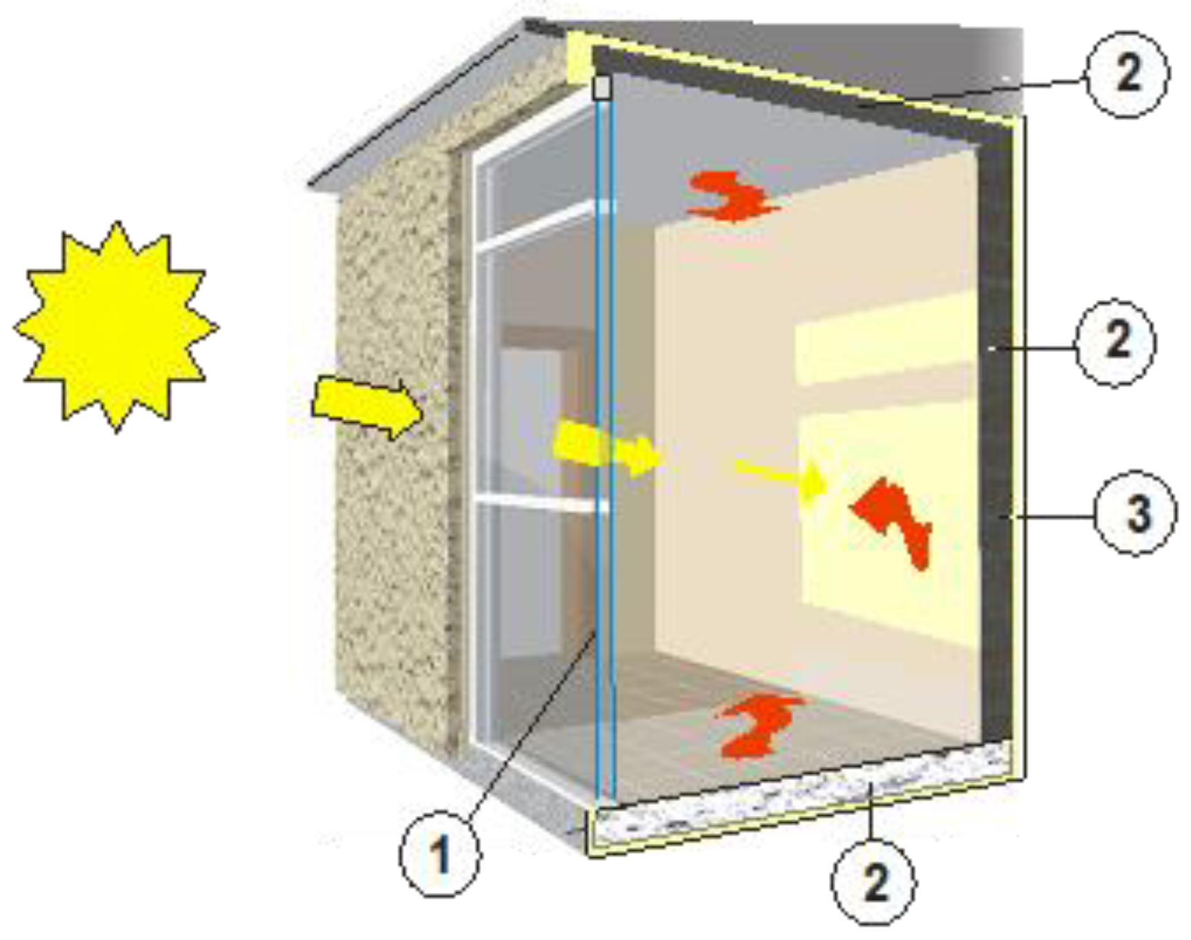
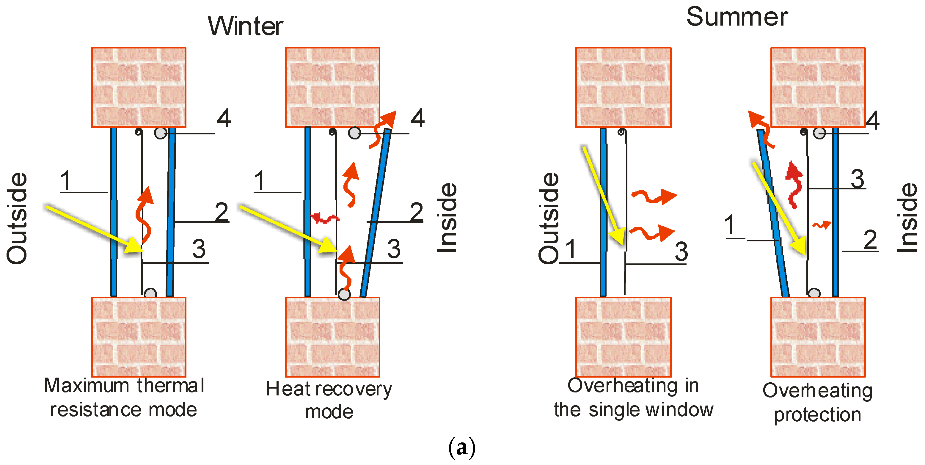
Considerable potential in the area of rational use of solar radiation in direct solar gain systems is seen in the modern double-glazed box windows [42] or a relevant modification of existing windows. Szyszka et al. [43] proposed a method to improve the insulating properties of windows or even an alternative to their replacement when a building is thermo-modernized using the concept of a quasi-box window. The idea is to install a new window from the inside of the building next to the old one (Figure 3).
The resulting quasi-box window has a higher thermal resistance than a single window. On sunny days, heat accumulates in the space thus created, which depending on the thermal capacity of the unit can reheat the adjacent room, also for a few hours after sunset (Figure 3b,c). This is why in [44,45] the installation of a container with PCM inside the window unit gap was proposed. Additional advantages of the box include efficient protection against overheating when interior shading elements are used. Owing to the tilted external window with the internal one closed the heat absorbed by the rolled-down blind is emitted outside, while protection against heated outdoor air is preserved (Figure 3b,c).
In their tests on an innovative double-skin ventilated window integrated with air purifying blind, Wang et al. [46] demonstrated that, compared to a shading blind, optimizing the inclination angle of the louvers and the position of the shutters used in winter and summer may improve the thermal and visual comfort and generate energy savings at the level of 23.9 kWh/m2 in the winter and 78.8 kWh/m2 in the summer.
2.2. Indirect Solar Gain Systems—Trombe Walls
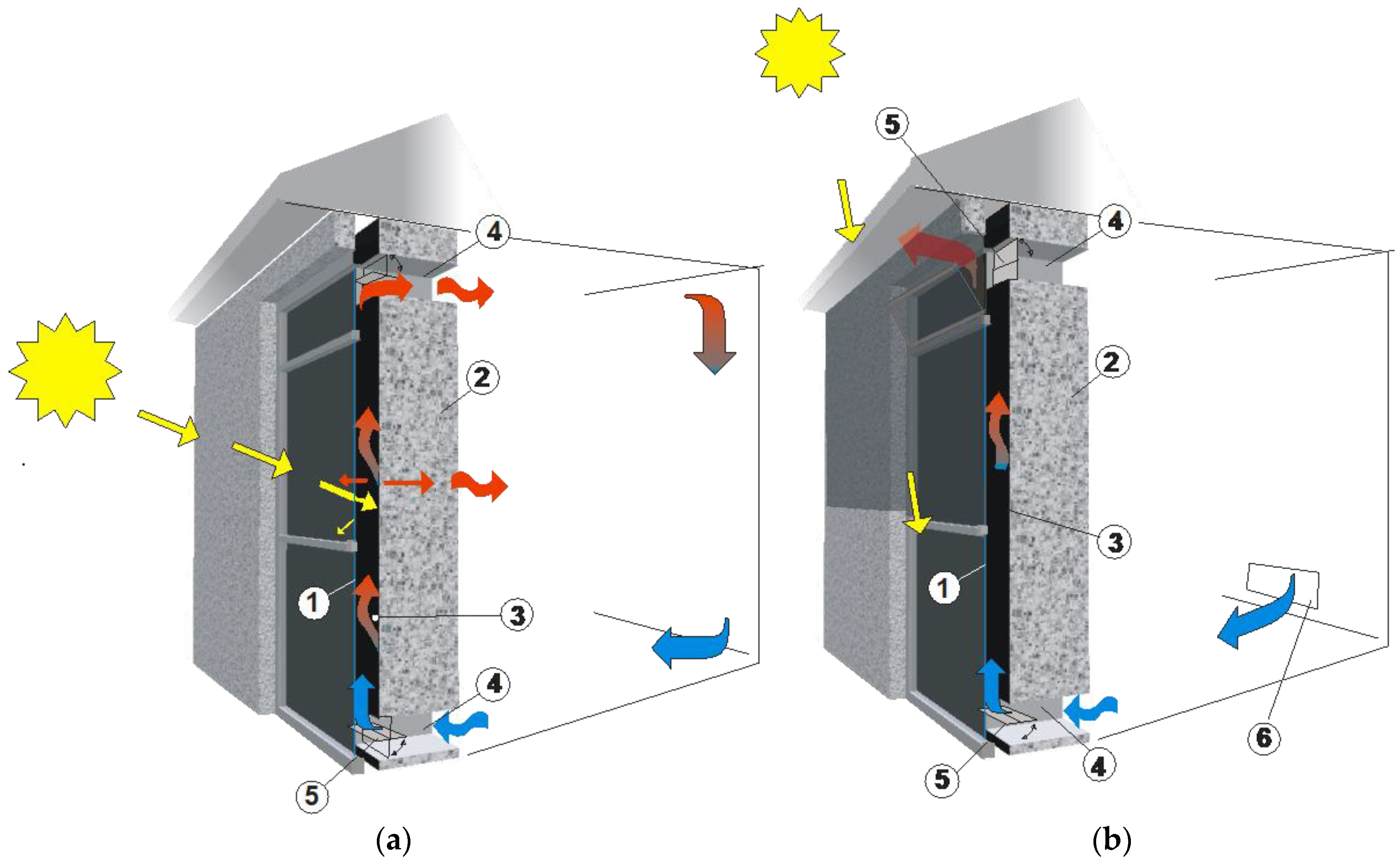
A way to solve problems related to the management of heat gains accumulated in a short time in direct systems is by using the concept of an indirect gains system (IGS). The most common example is the Trombe wall). In this solution, the solar gains are transferred to the building using the so-called thermal mass, usually the wall behind the glazing. By absorbing solar radiation, the wall stores it and then transfers it with a certain delay to the usable space by conduction (Figure 4a). Such location of the thermal mass is also beneficial in the summer, as it minimizes the risk of overheating the rooms. Furthermore, due to the chimney effect, it allows more intensive ventilation of the building with cool air drawn in from the north (Figure 4b).
The name Trombe Wall (TW) derives from the name of Felix Trombe, the co-creator of the solution, who, together with Jaques Michel, used it for the first time in 1967 in a building in Odeillo, France [47] and patented it in 1973 [48,49]. In many publications, the originality of the concept is attributed to Edward S. Morse, who in 1881, in the patent application ‘Warming and ventilating apartments by the Sun’s rays” (Figure 5), reserved the type of collector in which solar heat absorbed on a flat or corrugated plate is transferred to a building through vents with circulating air. On the other hand, Trombe Wall, in addition to its ability to heat air in the space behind the glazing, also has the ability to store heat, which is released with a delay depending on the thermal mass of the wall material (Figure 6).
The period of development of the idea of TW was tied in with the energy-efficient construction trend connected with the oil crises of 1973 and 1979. The co-author of the patent, Jaques Michel, explained the main assumptions of the design of TW in a French journal devoted to modern architecture called Architecture d’Aujourd’hui in 1973 [50]. Since then, the wall, as potentially one of the cheapest passive heating systems, has been discussed in numerous research projects across the world and is subject to modifications to improve its thermal efficiency in terms of climatic conditions and functionality [51,52,53,54,55]. TW can be designed as a wall in new buildings [56,57] or as a supplementation to thermal upgrading systems in existing buildings [58,59,60,61,62].
The thermal efficiency of the classical variants of TW is determined by the properties of its components (glazing, wall, absorption layer or absorber, and other additional interacting devices and elements, e.g., movable insulation, shading, etc.). The TW structure should be optimized by taking into account specific climatic conditions, orientation relative to the cardinal directions [63,64], the profile of daily energy demand, the season of the year, and the function of the building. Glazing has a great influence on shaping the heat balance. The criteria for selecting its parameters are analogous to those used in indirect systems. The selection of optimal glazing is really about finding a compromise in given climatic conditions between its properties of transmitting solar radiation and thermal insulation. For instance, Koyunbaba and Yilmaz [57], in the climate conditions of Izmir, Turkey, performed experiments to compare Trombe walls in which various types of glazing were used: single, double, and integrated with a photovoltaic panel. The results of tests indicated that the application of a double-glazed unit reduces heat loss but effects lower solar gains compared with single gazed units. Consequently, the researchers recommended the application of a single-glazed unit combined with movable night insulation. Kisilewicz [65], on the other hand, on the basis of simulation calculations performed for the climate in Poland, recommends the use of glazing with high thermal insulation glazing. He concludes that the thermal resistance of the glazing has a favorable and significant impact on the heating demand. Two-chambered and triple-pane glazing would reduce the demand for heating the adjacent space between 53 and 58% compared to an opaque and well-insulated wall. For the building analyzed, the reduction in heat demand reduction was 14%. The author indicates that a further reduction of heating demand, and also cooling demand, requires an exchange of the indoor air between the thermal zones of the building.
Although the thermal mass restricts temperature fluctuations caused by solar operation, Trombe walls, similar to direct solar gain systems, require protection against overheating in summer. In their study of a classical Trombe wall under moderate climate conditions in Italy, Stazi et al. [66] evaluated three assembly variants: a single glass pane, a glass pane with a Low-E coating, and a double-glazed glass pane. The results indicated that energy consumption can be reduced by up to 55% if the classical TW configuration (a 40 cm thick with single glazing) was replaced by an optimized configuration composed of double glass panes and a wall of small aerated concrete blocks 20 cm thick). A similar effect of double glazing on improving wall heat balance was indicated by the study by Dong et al. [67] and Zhang et al. [68].
In order to increase the thermal insulating capacity of the wall in winter and to prevent its overheating in summer, the use of movable insulation, as in direct solar gain systems, is recommended. The field tests carried out by Miąsik et al. [69] showed a reduction of the mean heat flux by ca. 77% in summer, while in winter energy consumption was observed at the level of a wall of the heat transfer coefficient of U = 0.3 W/m2K.
It should be noted that modification of roller blinds and shutters by the introduction of reflective coatings can improve their favorable operation. The coatings effectively reflect a considerable volume of heat that escapes through the wall. Opening reflective blinds or shutters at an adequate angle can intensify the absorption of solar radiation reflected from their surfaces to the TW absorber [70,71,72].
In unvented walls, the glazing is spaced close to the absorber to minimize the heat loss resulting from the convective exchange between the absorber and the glazing. This distance should be adopted following Torcellini et al. in the range of 2–5 cm [73], while according to Hordeski in the range of 3–6 cm [74]. In Zrikemet et al. [75], to minimize heat loss through a transparent partition, the elimination of the gap and placement of a honeycomb-like structure between the glass pane and the wall were proposed.
In an unventilated wall, heat is distributed by means of conduction within the wall. After the thermal wave has reached the inner surface, heat is released to the adjacent space as a result of radiation and natural convection. This phenomenon can take several dozen hours. It depends on the amount of radiation absorbed, the thickness of the wall, and its physical parameters [76,77].
Materials for the construction of this type of wall are selected based on the fundamental criterion of their high thermal capacity [28]. Most frequently it is concrete, stone, and brick [78], and the wall thickness is adopted in the range of 10 to 41 cm [73]. The thicker the wall, the higher its heat storage capacity; owing to solar radiation absorption, temperature fluctuations on the inner surface decrease. Since the outer surface of the wall is responsible for absorbing solar radiation, improvements are made to its absorbability are undertaken. One of the simplest is to apply a coating based on black or dark matt paint, which results in an absorbability of 0.95 [79]. The studies performed by Özbalta et al. [80] demonstrated the effect of the absorber color on the Trombe wall’s effective operation. The annual energy gains reached by the use of a wall painted with the darkest paints were found to be nearly three times higher than those obtained by the use of light colors.
The emissivity of the paint coats is proportional to their absorbability. A method to restrict the heat loss connected with it, resulting from radiation exchange to the environment, is the application of a selective coat [81]. It has a lower emissivity while a high absorbability is maintained. It is made, among other things, on a steel, aluminum, or copper sheet fixed to the outer surface of the wall. For example, a selective coat of black zinc made on galvanized steel has an absorbability of α = 0.96, with an emissivity of ε = 0.12 [76]. In papers by Čekon et al. [82,83,84], an innovative selective absorber whose properties enable solar gain control is presented (Figure 7a). The results of studies by Zhou et al. [85] indicated a favorable effect on the absorber’s ability to absorb heat owing to the use of longitudinal vortex generators(Figure 7b) to improve the performance of PCM—Trombe wall systems.
In the classical Trombe wall, an important part of heat distribution to a building is connected with the circulating flux of air heated by the solar radiation absorbed on the wall surface. Effective circulation, especially when natural convection occurs, is affected by the width of the air gap between the glazing and the absorber. This dimension should be selected to reduce air drag. According to Sparrow et al. [86], the width of the space between the glazing and the absorber must be greater than 4.7 cm.
According to Bin et al. [87], the application of circulation vents in a cool climate can improve the efficiency and functionality of the solution. Owing to the ability to absorb heat reception from the heated absorber, the possibility of an excessive increase in its temperature can be restricted, and consequently, heat loss through glazing. According to the calculations quoted in [87], in massive walls with a thickness exceeding 35 cm, the contribution of ventilation in the heat transfer to an adjacent space is assessed at the level of 70% compared to heat conduction. However, vents must be protected against reverse circulation [88]. A 10% to 20% capacity increase [89] can be obtained by the application of closeable flaps, dampers, special foils] and similar solutions. According to [90,91,92,93,94,95,96] heat transfer efficiency via circulation is strictly connected with the construction of the wall and optimization of the time of opening and closing the flaps of circulation vents.
Results of the research on the effect of the application of a ventilated Trombe wall in a building envelope on the level of energy savings differ. In their analyzes performed with ENERGY Plus program for the climate in France (Lyon), Bojić et al. [97] show these savings at the level of 20%. The same level of energy savings is also confirmed, presented in [87], by the results of measurements taken on an actual object in Zion National Park (Utah, USA). On the other hand, in the article by Nowzari et al. [98] the presented results of the analyses performed in TRNSYS (Transient System Simulation) of a 120 m2 building with a 15 m2 Trombe wall in the climatic conditions of Cyprus indicate a reduction in the heat demand at the level of approximately 45%. Moreover, analysis of life-cycle cost (LCC) demonstrated that the construction of this type of wall is more economical than the purchase of a 3 kW gas-fired boiler. Similar results of simulations performed under the corresponding climatic conditions were obtained by Kalogirou et al. [99]. A 25 cm thick south-facing wall reduced the energy demand for heating a model building by about 47%. The study conducted by Dimassini [100] in the climate indicated the efficiency of a ventilated wall in the range of 31.7–45%. Fang showed a similar 30.2% efficiency of a collector-accumulation wall in the conditions typical of the period November–March in Beijing, China, [101,102]. In the period of January to April, as a result of optimization with TRNSYS of a ventilated Trombe wall referring to the surface of the southern wall, with the aim of achieving maximum energy consumption reduction, Jaber et al. [103] evaluated the maximal energy savings at 37.55%. This value corresponded to a 37% contribution of TW in the area of the southern wall.
2.2.1. Trombe Walls of Increased Thermal Resistance
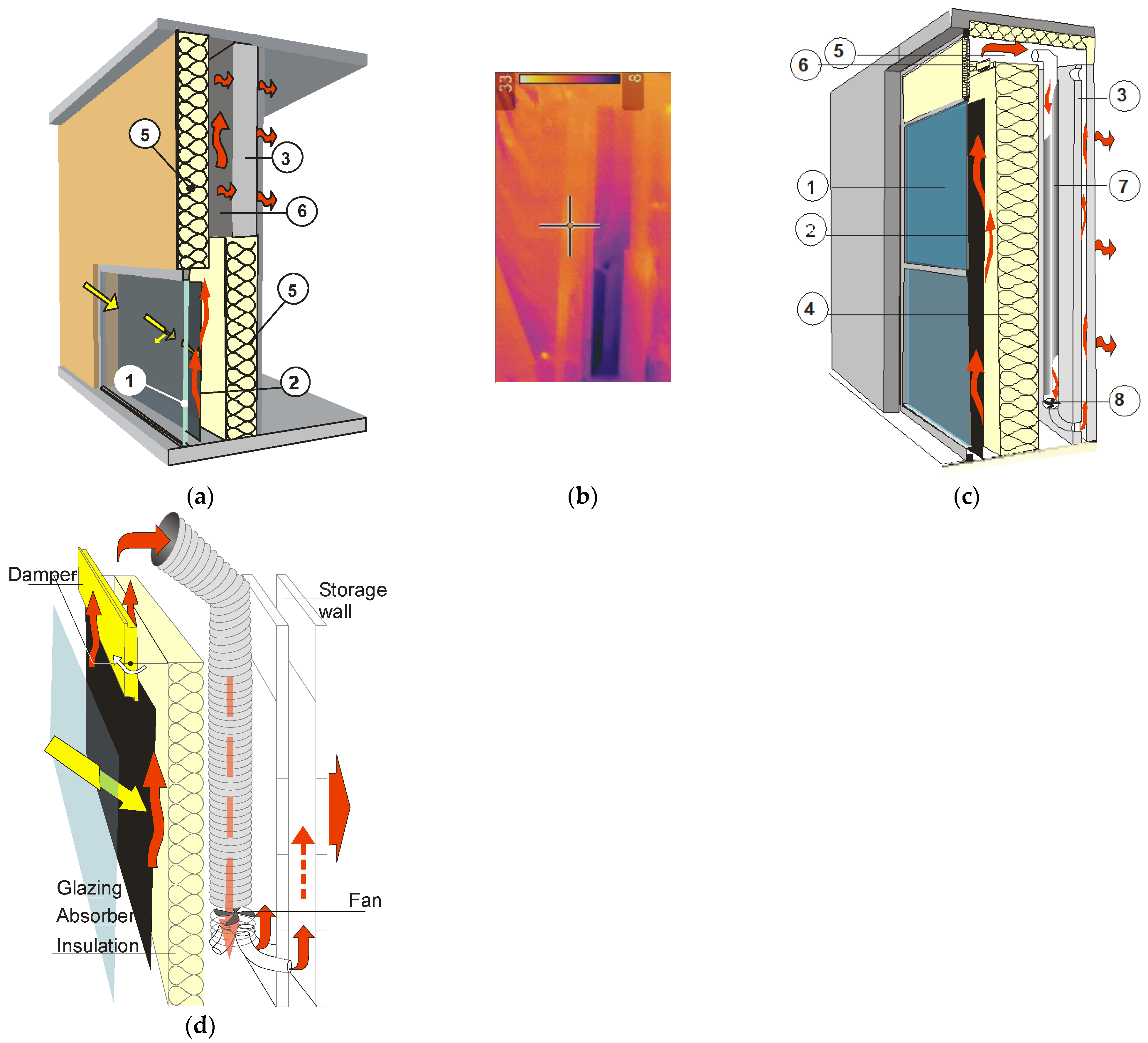
The above-outlined review of research on the classical Trombe wall illustrates its noticeable potential to improve heat balance, particularly in a climate of considerable and regular solar irradiance. In moderate and cool climates, with low temperatures in winter, with very irregular solar irradiance, it is necessary to apply solutions limiting the risk of significant heat loss not only at night, but also in a prolonged period of low solar irradiance. A method of reducing this problem is to modify a TW by embedding an additional insulation layer. In the solution presented in [104] a 10 cm thermal insulation layer was placed between the selective absorber and the wall (Figure 8a). Numerical simulations of the operation were performed for the climatic data of the city of Xining in Qinghai province, China. The difference in the functioning of the prototype compared to the classical wall operating under identical conditions was defined. The efficiency of the solution calculated as the ratio between the heat entering a space and the total solar irradiance reaching the wall was 33.85%, which was an increase of 56% compared with the efficiency of the classical Trombe wall of 21.69%. The authors concluded that the heat gain distribution was determined by the air flux that circulates between the absorber and the room. The impact of conduction within the wall was assessed as practically negligible. In [105] Chen W., in turn, proposed to use a porous absorber which, compared to the typical solution, improves the mean temperature and can also play the role of thermal semi-insulation.
In another solution, the so-called composite TW [90,106], the thermal resistance was improved by installing an additional thermal insulation wall with air vents behind the masonry (Figure 8b).
According to the authors, the advantages of the solution include the possibility of regulating the heating intensity by controlling the air transfer in the circulation duct and a higher efficiency of the composite wall compared to the classical Trombe wall which functions in cool and moderate climates. An additional 3.7% improvement in the efficiency of the solution can be reached by way of the optimization of the way heated air circulates [107].
The location of thermal insulation on the interior of the building, in a cool and moderate climate during the prolonged period of cloud cover and low temperature, may pose a risk of condensation of water vapor in the air gap [108,109]. Periodic dampness of the gap surface during long-term operation poses a risk of mold development and air pollution of the building with circulating air.
2.2.2. Unvented Trombe Wall
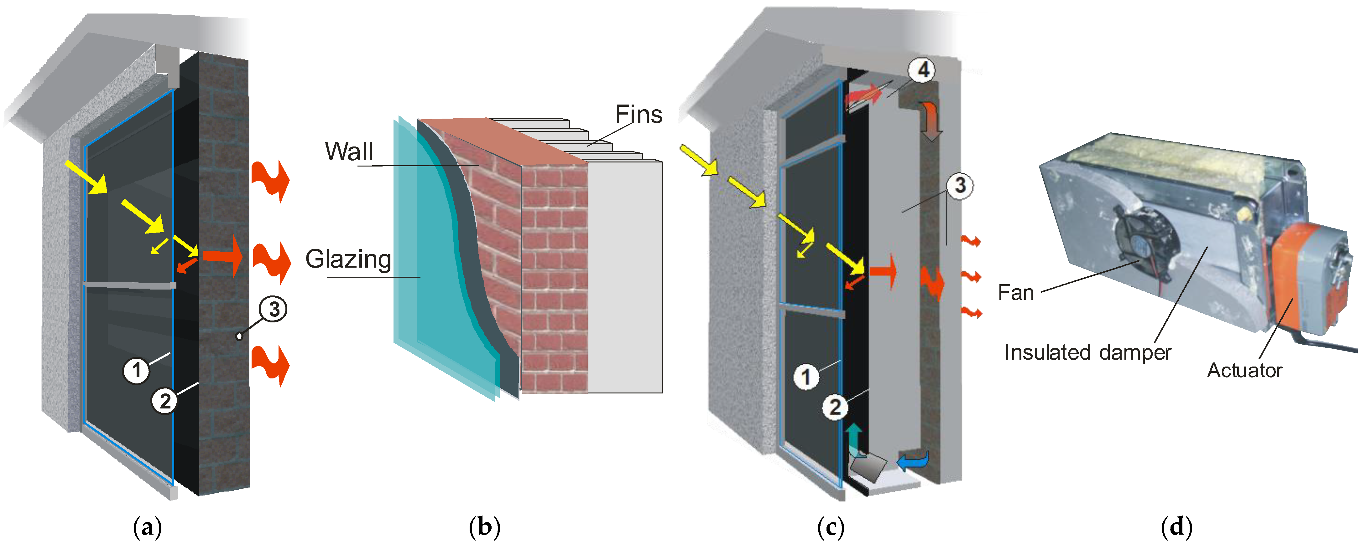
In unvented walls, the heat stored in the mass wall is distributed indoors only by way of conduction. Examples of such a solution include an unvented TW, Slotted Trombe wall, Thermo-Diode Trombe Wall (TDTW) and Interactive Trombe Wall (Figure 9 and Figure 10).
The classical unvented Trombe wall (Figure 9a) consists of a wall separated from the exterior glazing by an unvented air gap. The simple design and low cost of the solution are its main advantages. The control of heat exchange with the building is reduced to an adequate selection of the thermal mass. For this reason, the solution is intended for a climate with regular solar irradiance and large daily temperature amplitude. The functioning of a wall without insulating glazing and no additional movable thermal insulation exposes the adjacent spaces to uncontrolled heat loss in winter and overheating in summer [65,69]. The heat balance of the walls can be improved by installing special fins (Figure 9b), which can improve thermal performance compared to a smooth surface by up to 7% [110].
In order to improve thermal insulation and internal heat distribution in the wall, the so-called collector-accumulation slotted wall, in work [109], it was proposed to divide the brick part into two parts (24 cm and 12 cm) separated by an internal gap (Figure 9c). This gap is connected by internal ventilation openings with an air gap between the absorber and the glazing. During the heating of the absorber, part of the heat is transferred and accumulated in the outer part of the wall, while the remaining amount of heat heats the wall from the inside as a result of the internal circulation of heated air between the gaps. Mounted inside the integrated vents, the dampers with the fan (Figure 9d) intensified the circulation of the heated air or when closed prevented the reverse cooling of the inner duct. In the tests on the slotted collector-storage wall, the mass wall was made of sand-lime brick, concrete blocks, and hollow cellular concrete bricks with a density of 800 kg/m3. The tests indicated a recovery efficiency of heat from solar radiation of 28, 25, and 17.5%, respectively. The heat transfer coefficient determined in the experiment was 0.5, 0.8, and 0.3 W/m2K, respectively.
The improvement of the thermal insulating capacity of unvented walls by means of insulating glazing, movable insulation, and other similar solutions has obvious limitations. In cool and moderate climates the noticeable improvement of the thermal balance of both direct heat gains and Trombe walls may result from considerable gains reached in short-duration periods of very intensive solar radiation. However, prolonged periods of cloud cover occur during which walls are exposed to bigger heat loss than typical walls insulated thermally to the level regulated by technical specifications obligatory in a given country. The higher heat transfer coefficient of TW may cause investors to be concerned about the need to meet higher heating costs when low radiation does not bring expected heat gains. The starting point adopted in the Thermo-Diode Trombe Wall (TDTW) (Figure 10a) [109,111,112] was that the thermal insulation capacity should not be lower than compulsory for typical walls with thermal insulation. The operation principle of TDTW is based on the phenomenon of thermal stratification of air (Figure 10b). The heat generated as a result of the absorption of solar radiation by an absorber placed in the lower section of the wall is transported, by natural convection, to the upper section where it is taken over by the masonry and transferred to the indoor space by way of conduction. In field tests performed in the climatic conditions of Rzeszów city (Poland) on a clear-sky day, the thermal energy provided to the indoor room was 207.7 Wh/m2 compared to 36.0 Wh/m2 lost toward the air cavity. On days with very little sunshine, TDTW was unable to generate any significant heat gains, but the high insulation power meant that the heat loss to the outdoor environment was not greater than that of a wall insulated thermally.
In another solution related to biomimetics, the so-called Interactive Trombe Wall (ITW) (Figure 10c) [113] has the ability to react interactively to weather conditions by changing the internal distribution of heat flow. During insolation, the heated air is transferred to the wall accumulation and distribution section through a forced circulation system using a fan driven by a photovoltaic panel. The circulation system integrated with the damper (Figure 10d) automatically reacts to external conditions, optimizing the recovery of solar gains and protecting against cooling down in winter and overheating in summer. Field tests carried out in the climate of the city of Rzeszów showed an average efficiency of solar radiation conversion into heat gains at the level of 20%.
2.2.3. A Wall Modified with a Phase Changing Material (PCM)—TW
One of the methods of improving the heat capacity of the partition is to modify its structure by means of a phase-changing material whose change of state requires exceeding the so-called phase transition temperature (melting temperature). This phenomenon is accompanied by the intake of energy, which is released when the material returns to its original state. The phase-transition energy is defined relative to a unit of mass or volume. In the case of paraffins and organic compounds, it reaches a value of up to 250 kJ/dm3, while in the case of salt hydrates it reaches 400 kJ/dm3 [77,114,115,116]. The basic parameters that characterize these materials include the phase-transition heat (latent heat) and the phase-transition temperature. The condition for PCM application is its activity at temperatures that allow the phase transition [117]. In the case of collector-accumulation walls, the temperatures in specified cross sections are affected by the temperature of the air on both sides of the wall, solar irradiation, and the type of materials from which the wall components were made.
The benefits of the application of PCM include the check of temperature fluctuations, and improving the comfort of using the room adjacent to the wall. In [118] attention was drawn to the fact that walls containing a phase change material require less space and are lighter compared to massive walls of the same heat capacity. This property may be of particular significance in the case of very high costs of useful floor space.
On the basis of numerical analyzes performed by Bourdeau [119] cited in [118] a 0.15 m concrete wall can be substituted by a wall made for a phase change material of merely 3.5 cm thick at identical heat capacity.
Performing analyses of hydrated capsulated salt, Khalifa and Abbas [120] found that an 8 cm wall containing hydrated salt has a better heat accumulation capacity than a 20 cm concrete wall. Moreover, the amplitude of the PCM wall reduced the temperature fluctuations by 3 °C and released heat at night twice as long as the concrete wall [120]
Based on numerical simulations performed in the Wuhan climate of Wuhan(China), Zhu et al. [121] found that the application of PCM in envelope elements can reduce peak cooling load by 9% and heating load by 15%, compared to conventional.
Based on a review of more than 200 articles on the use of PCM in buildings, including those integrated with TW, Zeinelabdein, et al. [122] confirm the significant potential of using PCM for energy storage in buildings. However, he notes that there is not enough research to representatively assess the durability of this technology and is seeing a threat to its dissemination because of the drawbacks among which he includes segregation, excessive cooling, low thermal conductivity, and high cost.
2.2.4. Trombe Wall Integrated with Photovoltaics
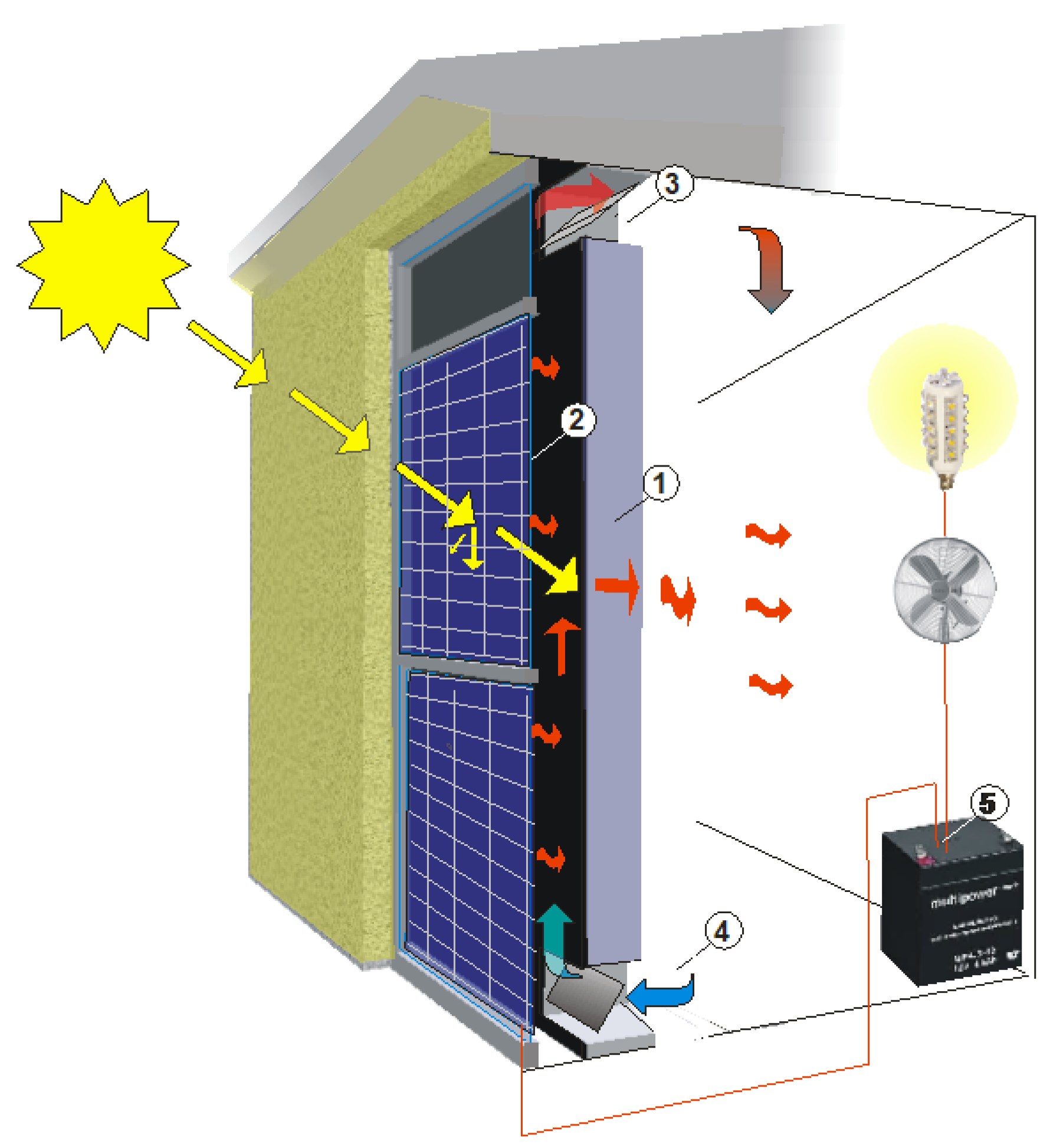
About 80% of the surface of the solar energy reaching the photovoltaic cell is converted into thermal energy, but an increase in the temperature of photovoltaic cells results in a reduction in their efficiency [123,124,125,126]. The efficiency of the photoelectric conversion of PV cells can be improved by placing the PV panel in the transparent envelope plane (Figure 11), due to which the heat is released from its rear part to circulating air flux. This heat can be released to an adjacent room or transferred outdoors. It is estimated that this type of cooling may reduce the cell temperature by up to 15 °C and increase its efficiency by more than 8% [127]. The studies performed by Jie et al. [128] indicate that cell cooling improved the efficiency of their photoelectric conversion by 5%. In their studies on the efficiency of a BIPV wall in a residential building equipped with a semi-transparent Si solar cell, Koyunbaba et al. [57] demonstrated that an average daily thermal efficiency at the level of 27.2%, and photovoltaic at 4.52% can be obtained.
2.2.5. Solutions for Extending the Functionality of a TW
Solutions to extend the functionality of a TW include solutions devoted to improving hygiene and sanitary conditions. One of these is catalytic TW which, due to photocatalytic reaction has the concentration of ability to reduce the formaldehyde in air [129]. Compared to the traditional solar Trombe wall, the new photocatalytic Trombe wall contains composite crawler-type modules SiO2/TiO2 placed between the external glass unit and the inner wall. A single module consists of circular ducts as shown in Figure 12. which have an area with composite material SiO2/TiO2 and an area with TiO2 only. The main function of the former one is the adsorption and desorption of water molecules and formaldehyde. The function of the second concerns the photocatalytic degradation of formaldehyde. When the adsorption modules rotate inward, the humid air containing formaldehyde particles is absorbed into the circular ducts. Water vapor and formaldehyde are desorbed by adsorptive SiO2/TiO2. On the outside, on the other hand, the water and formaldehyde are desorbed because of the growth of temperature of the adsorption modules. The desorbed water vapor flows out and formaldehyde is decomposed by TiO2 into CO2 and H2O under the influence of solar radiation [129].
The results of studies presented in [130,131] indicate that apart from the average daily electrical efficiency of 11.9% and the thermal efficiency of 36.6%, the wall has air purification ability at the level of 42.5–81.6 m3/h. In another concept, the high values of temperature and UV radiation in the air gap between the glazing and absorber are used for the inactivation of viruses present in the flux of heated convectively circulating air. The maximum single-pass inactivation ratio was 0.893 [132].
2.2.6. Transparent Mixed Systems
A special case of the discussed systems is illustrated by solutions that combine the properties of indirect and direct systems. These can include, among others, the Trombe wall water Trombe (WTW) [133], (Figure 13), interactive transparent TW (Figure 14), or Balcombe system with a buffer space (Figure 15).
The specific heat of water is very large, more than four times that of masonry materials. Its application in the accumulation layer increases the thermal capacity. However, the use of water is inconvenient as it requires the use of watertight containers. The transparent water container, made most frequently of glass (Figure 13) functions as a light-transmitting wall [52,133,134]. Its interior is filled with colored water and contains biocidal products which antagonize microbial development. Additionally, an absorptive glass pane and semitransparent elements are placed inside the glazing, whose function is stiffening the structure, absorption, and sunlight diffusion. The use of this solution requires protection means against excessive loss or overheating, just as in direct solar gain systems.
The idea of an interactive transparent TW (Figure 14), also known as an Interactive Glass Wall, [135] is based on the construction of a wall made of three layers of composite glazed units: outside, inside, and middle produced in the louver window technology. During the operation of sun radiation, once the designed level of air temperature inside the partition is exceeded, the actuator makes the louver windows open and the perforated absorbers fixed to them are exposed. The generated heat is accumulated in the tubular containers with PCM, spaced circumferentially, owing to which the heat can be released to the building even at night. Due to the application of two-chambered composite glass units in the IGW structure, the heat transfer coefficient reached the value of U = 0.167 W/m2K in closed louver windows and 0.255 W/m2K when they are opened.
The solution combining the properties of direct and indirect systems is illustrated by the Balcombe system with buffer space (Figure 15). After the transition through the glazing of the outhouse, solar radiation heats the building. At the same time, it is absorbed and accumulated in the thermal mass of the buffer space from where it reheats the building at a later time.
An advantage of the system with a buffer space is that the existing building can be adapted easily and in a simple way [136]. Apart from upgraded thermal comfort, it obviously reduces heat loss and ensures additional supporting space. Chwieduk [136] points out the need to provide ventilation to reduce the risk of increasing humidity that results in the development of mold and fungi during prolonged cloudiness and low temperatures.
Buffer systems also include a double-skin façade (DSF) used in office buildings [137,138,139,140]. It is a vertical exterior partition made up of two glazings separated from each other by an air gap that also functions as a ventilated air duct [141]. The numerical simulations of DSF operation performed in [142] demonstrate the potential of DSF to save energy for both heating and cooling a building.
2.3. Protection of Indirect Systems against Overheating in the Summertime
Although the thermal mass used in indirect systems reduces the risk of overheating rooms in the summer, such a scenario is not eliminated completely. Therefore, protection methods used in direct systems, such as movable insulation, are recommended, for instance. Taking into account the incidence of the angle of the solar radiation in this period, the installation of shading elements, ie, louvers, roller blinds, roof overhangs, shutters [73,143,144], or a canopy that can be integrated into a solar or PV panel is also rational. An interesting alternative for movable insulation in the aspect of partition operation in the summer is illustrated by the possibility of shading it with climbing plants dropping their leaves before the winter (e.g., Parthenocissus tricuspidata or quinquefolia, legumes, etc.). In [71] the efficiency of various types of shading was described on an unvented Trombe wall. It was shown that the application of adequately designed roof overhangs can reduce wall heating in the range of 29.7% to 44.4%. Roller blind efficiency was found higher than 58.0% to 63.2%. The best result, reaching 72.6%, was obtained by combining the two methods. Cooling can be intensified through the stack effect [51].
According to studies performed by Balocco [145], a favorable effect of solar cooling in the summer is determined by the width of the air gap in front of the absorber, which should be at least 7 cm. Increasing this distance to 35 cm can result in an increase in cooling efficiency in the summer by 20%. In the Chen studies carried out by the team [18] the validity of the installation of a roller blind in the space between the glazing and the absorber. The function of this roller blade is, in addition to reducing heat loss, a reduction of heat convective exchange.
2.4. Efficiency of Indirect Systems
The efficiency of a solar gain system is defined as a ratio between the heat gains achieved and the value of solar irradiation that generated the gains [146]. As long as the assignment of value of irradiation reaching a wall surface does not give rise to doubts of interpretation, efficiency quantification is expressed in various ways: as energy savings refers to a reference variant [97,110], a rise of the average temperature of thermal mass, a level of equivalent reduction [66], a level of reduction of viruses or formaldehyde in the air [129,130], etc. The differences between efficiency referred to heat demand range on average from 25% [146] to more than 55% [66]. They mainly concern the case study in given climatic conditions, which makes it difficult to compare the efficiency of individual solutions and their objective evaluation with respect to usability or profitability in any climate.
Heat gains achieved from solar radiation are a component of the heat balance, apart from heat losses proportional to the difference in air temperature on both sides of the wall. This is why measurements taken over the longest possible period of time covering the widest possible range of changes in outdoor temperature are especially desired.
Information on the achieved effect in the form of heat gains specified in the most favorable conditions except during nighttime and cloud cover may be not representative of the evaluation of the system in the long term. The solutions that have a high instantaneous efficiency of heat recovery from solar radiation may at the same time generate unacceptable heat loss. Actual efficiency may also be limited by excess gains supplied over a too-short period. For this reason, in the evaluation of the Trombe wall, the so-called effectiveness of the heat supply from a Trombe wall is the load reduction efficiency parameter [147,148], expressing the ratio between the energy savings that result from the use of TW and the heat gains can be used.
The evaluation of the efficiency of the presented solutions is most frequently based on numerical simulations, in situ experimental studies employing test houses, test chambers that enable testing of prototypes in real or reduced scale, and a combination of the aforementioned methods.
Additional possibilities are offered by laboratory simulations. The research [69,149,150] uses the method of simulating the absorbed solar radiation using a heating cable with adjustable power connected to the absorber. They made it possible to observe thermal phenomena that occur under the conditions of a temperature gradient in selected cross-sections of the prototype. The studies performed following the theory of Design of Experiment (DoE) enable the presentation of the dependence of the dependent variable (e.g., efficiency) on the adopted independent variables (e.g., selected climatic parameters) in the form of function. The dependencies obtained in this way have a universal character in the area of the given domain of the experiment. The method described in [150] is not costly (e.g., compared with a test house or test chambers of large dimensions); instead it enables the optimization of the design of prototypes of the tested solutions within the range of the adopted criteria.
2.5. Synthesis of the Evolution of the Discussed Systems
The presented development of systems of recovering heat from solar radiation exemplified by selected solutions indicates their potential impact on the heat balance of buildings. The categorization of the systems into direct and indirect is arbitrary in nature. It concerns the time and place where the process of photothermal conversion of solar radiation into heat takes place. In direct systems, this process takes place directly indoors, whereas in indirect systems the heat is previously absorbed and accumulated outside before it reaches the interior. Windows, representing direct systems, have the highest instantaneous effectiveness of solar radiation conversion into heat that reaches their surface. However, the amount of heat supplied over a short period of time causes problems in its utilization, which can lead to overheating of rooms. Moreover, compared with thermally insulated walls, modern multiglazed windows may generate higher heat losses in periods of cloud cover and at night. In direct systems, the problems with heat exchange control reduce their applicability without additional protection measures such as movable insulation or shading elements. An alternative solution is offered by multifunctional double-glazed windows of the box design or the so-called quasi-box windows. When reducing the direct access of solar radiation to a building, they may be equipped with solutions to improve solar gain utilization capacity. In the context of a new product or a method of thermomodernization of existing windows, the development of this idea has research potential as a remedy for the problems of heat losses in the winter or energy demand for cooling in the summer with which large glazed surfaces are confronted.
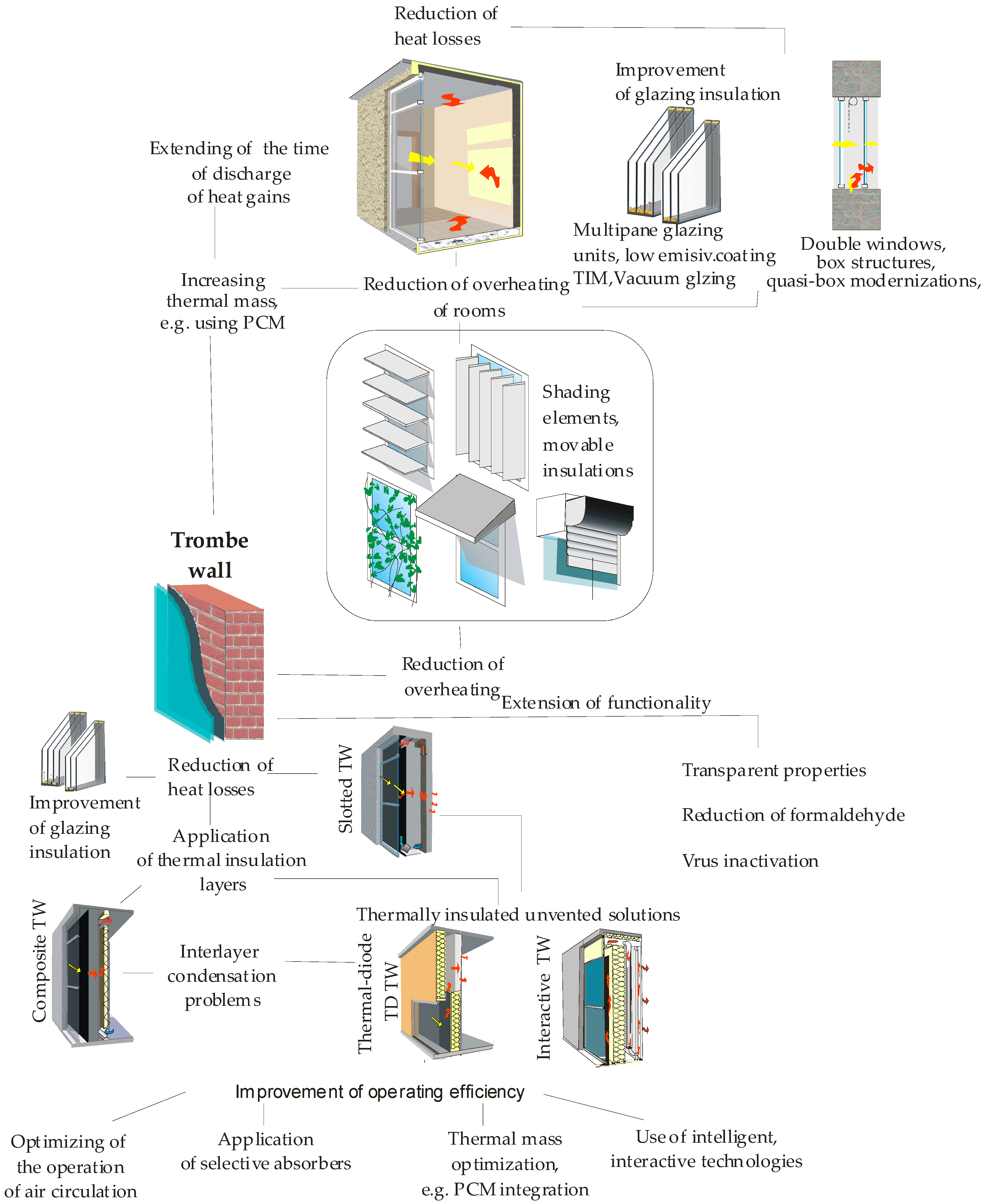
In indirect solar gain systems, because of the separation by the thermal mass of the interior from solar radiation transmitted through the glazing, the heat accumulation capacity and time of its distribution are increased. Unfortunately, in a cold or moderate climate, the classic design of the Trombe wall does not guarantee satisfactory protection against heat loss during period of insufficient solar radiation. The application of a thermal insulation layer in the so-called composite TWs reduces heat loss, but in a climate of considerably irregular solar radiation, in buildings of standard level of air humidity, it poses a threat of interlayer condensation and related phenomena of affecting the sanitary conditions in the building. Concerning the quality of air circulating in a space exposed to the risk of contamination development, in the thermodiode TW and an interactive TW this form of a heat exchange was abandoned. Heat is transmitted by means of conduction in the wall layer where it accumulates and is next transferred to the building as an effect of convection-radiation exchange between the outdoor environment and the wall surface. These are solutions of very high thermal resistance, in which, as assumed, the effectiveness of solar gains utilization is not improved at the cost of protection against unacceptable heat loss. In this aspect, a research area opens up concerning the implementation and optimization of interactive and intelligent solutions in the scope of thermal resistance automatic changes adequately to climatic conditions. A system scheme as a response to identified operational problems is shown in Figure 16 below:
Owing to a relatively simple design, low cost of manufacture, and simplicity of use the discussed solutions as wall elements integrated with the building’s exterior envelope are easily applicable in residential, industrial, or public utility buildings. Trombe walls may be an alternative for curtain walls that do not carry loads from the building’s elements above them. They can also be used for the thermal modernization of existing buildings in which a considerable glazing surface is an annoyance due to large heat losses or interior overheating. They can be integrated with windows or other elements of a building’s façade. Depending on the building’s function the thermal mass volume should be selected such that the time of heat gains discharge overlapped the hours of its basic use.
3. Conclusions
The results presented of research projects on systems that convert solar energy into heat indicate a great potential for the reduction of conventional energy demand in the building industry. It is of particular importance in the time of the global threat of energy deficiency. The modification methods of the windows and the classic Trombe wall indicated that they are appropriate to the identified problems of their use in given climatic conditions.
The highest peak efficiency is reached in direct solar gains systems (DSGS). However, what is the essential drawback of these solutions is the culmination in gains of heat transmitted by solar radiation in a short period of irradiation. This can result in overheating the interior rooms in the summer, even in the winter, and thermal discomfort for the rooms occupants. Additionally, in winter, large glazed areas increase the risk of unacceptable heat loss.
Apart from known and used methods of improving the heat balance of windows as an inseparable element of the building (movable insulation, shading, etc.), the rese-arch potential of double-glazed windows of box design or quasi-box windows should be exploited. Their integration with the interior elements of shading-absorption effects and heat accumulation (e.g. those containing PCM) may reduce temperature fluctuations in a building, as well as prolong the period of time when solar gains are discharged even after sunset.
The development review of indirect systems represented by the Trombe wall indicates significant changes compared to the original concept of 1967. Design modifications are a response to the global demand for the recovery of solar energy, reduction of conventional energy consumption, or improvement of air quality by the reduction of formaldehyde concentration or virus inactivation.
In the context of energy effects maximization, the selection of a TW optimal solution is strictly connected with climatic conditions.
In a mild or warm climate, the development of TW is focused on the optimization of recovered heat distribution and improvement of functioning in the summer. In a cold climate, the popularization of the solution is significantly hindered by the considerable irregularity of irradiation and concerns about heat losses in the periods of cloud cover or during the night. In this aspect, the solutions of high thermal resistance have a development potential. The direction of TW design development is determined by a combination of high thermal resistance and the capacity for solar heat recovery. Considering the availability of inexpensive and user-friendly control systems, attention should be paid to the applicability of solutions that fit the trends in intelligent construction, biomimetic solutions that interactively respond with a change in thermal resistance change to irradiation and temperature or user needs.
It is practically impossible to make a comparison of the efficiencies of individual solutions quoted in publications because they very often concern a case study connected with selected climatic conditions. Information on the heat gains of specific solutions presented in the articles is not of universal importance. It would be helpful to develop a method of presentation of efficiency as a function of climatic conditions, which could be a useful aid in decision-making processes as to the use of solutions and their dissemination. Such a project could be based on numerical and laboratory simulations together with statistical inference and the theory of design of experiment, or on long-term in situ tests covering the widest possible ranges of boundary conditions changeability.
Funding
This research received no external funding.
Data Availability Statement
Not applicable.
Conflicts of Interest
The authors declare no conflict of interest.
References
- Sizirici, B.; Fseha, Y.; Cho, C.-S.; Yildiz, I.; Byon, Y.-J. A Review of Carbon Footprint Reduction in Construction Industry, from Design to Operation. Materials 2021, 14, 6094. [Google Scholar] [CrossRef]
- Available online: https://ec.europa.eu/info/news/focus-energy-efficiency-buildings-2020-lut-17_en (accessed on 15 August 2022).
- Alotaibi, B.S.; Khan, S.A.; Abuhussain, M.A.; Al-Tamimi, N.; Elnaklah, R.; Kamal, M.A. Life Cycle Assessment of Embodied Carbon and Strategies for Decarbonization of a High-Rise Residential Building. Buildings 2022, 12, 1203. [Google Scholar] [CrossRef]
- Jäger, F. Solar Energy Applications in Houses Performance and Economics in Europe; Commission of the European Communities: Brussels, Belgium; Luxembourg, 1981. [Google Scholar]
- Mouratis, K.; Tudose, I.V.; Romanitan, C.; Pachiu, C.; Popescu, M.; Simistiras, G.; Couris, S.; Suchea, M.P.; Koudoumas, E. WO3 Films Grown by Spray Pyrolysis for Smart Windows Applications. Coatings 2022, 12, 545. [Google Scholar] [CrossRef]
- Teixeira, H.; Gomes, M.G.; Moret Rodrigues, A.; Aelenei, D. Assessment of the visual, thermal and energy performance of static vs. thermochromic double-glazing under different European climates. Build. Environ. 2022, 217, 109115. [Google Scholar] [CrossRef]
- Essa, F.A.; Abdullah, A.; Majdi, H.S.; Basem, A.; Dhahad, H.A.; Omara, Z.M.; Mohammed, S.A.; Alawee, W.H.; Ezzi, A.A.; Yusaf, T. Parameters Affecting the Efficiency of Solar Stills—Recent Review. Sustainability 2022, 14, 10668. [Google Scholar] [CrossRef]
- Pracucci, A.; Magnani, S.; Casadei, O. The Integration of Vacuum Insulated Glass in Unitized Façade for the Development of Innovative Lightweight and Highly Insulating Energy Efficient Building Envelope—The Results of Eensulate Façade System Design. Designs 2020, 4, 40. [Google Scholar] [CrossRef]
- Baek, S.; Kim, S. Optimum Design and Energy Performance of Hybrid Triple Glazing System with Vacuum and Carbon Dioxide Filled Gap. Sustainability 2019, 11, 5543. [Google Scholar] [CrossRef] [Green Version]
- Shi, Y.; Xi, X.; Zhang, Y.; Xu, H.; Zhang, J.; Zhang, R. Prediction and Analysis of the Thermal Performance of Composite Vacuum Glazing. Energies 2021, 14, 5769. [Google Scholar] [CrossRef]
- Aguilar-Santana, J.L.; Jarimi, H.; Velasco-Carrasco, M.; Riffat, S. Review on window-glazing technologies and future prospects. Int. J. Low-Carbon Technol. 2020, 15, 112–120. [Google Scholar] [CrossRef]
- Saleh, M.A.; Kaseb, S.; El-Refaie, M.F. Glass–azimuth modification to reform direct solar heat gain. Build. Environ. 2004, 39, 653–659. [Google Scholar] [CrossRef]
- Paneri, A.; Wong, I.L.; Burek, S. Transparent insulation materials: An overview on past, present and future developments. Sol. Energy 2019, 184, 59–83. [Google Scholar] [CrossRef] [Green Version]
- Abdelrady, A.; Abdelhafez, M.H.H.; Ragab, A. Use of Insulation Based on Nanomaterials to Improve Energy Efficiency of Residential Buildings in a Hot Desert Climate. Sustainability 2021, 13, 5266. [Google Scholar] [CrossRef]
- Buratti, C.; Moretti, E.; Zinzi, M. High Energy-Efficient Windows with Silica Aerogel for Building Refurbishment: Experimental Characterization and Preliminary Simulations in Different Climate Conditions. Buildings 2017, 7, 8. [Google Scholar] [CrossRef] [Green Version]
- Struhala, K.; Čekon, M.; Slávik, R. Life Cycle Assessment of Solar Façade Concepts Based on Transparent Insulation Materials. Sustainability 2018, 10, 4212. [Google Scholar] [CrossRef] [Green Version]
- Marrone, P.; Asdrubali, F.; Venanzi, D.; Orsini, F.; Evangelisti, L.; Guattari, C.; de Lieto Vollaro, R.; Fontana, L.; Grazieschi, G.; Matteucci, P.; et al. On the Retrofit of Existing Buildings with Aerogel Panels: Energy, Environmental and Economic Issues. Energies 2021, 14, 1276. [Google Scholar] [CrossRef]
- Chen, B.; Chen, X.; Ding, Y.H.; Jia, X. Shading effects on the winter thermal performance of the Trombe wall air gap: An experimental study in Dalian. Renew. Energy 2006, 31, 1961–1971. [Google Scholar] [CrossRef]
- Löhnert, G. Thermal Insulation and Shading System—TWS: An Improvement of "Beadwall" Principle. In Advances in Solar Energy Technology; Bloss, W.H., Pfisterer, F., Eds.; Pergamon: Oxford, UK, 1988; pp. 3508–3513. [Google Scholar]
- Huang, Y.; Niu, J.L.; Chung, T.M. Energy and carbon emission payback analysis for energy-efficient retrofitting in buildings—Overhang shading option. Energy Build. 2012, 44, 4–103. [Google Scholar] [CrossRef]
- Bhatia, A.; Abhilash, S.; Sangireddy, R.; Garg, V. An approach to calculate the equivalent solar heat gain coefficient of glass windows with fixed and dynamic shading in tropical climates. J. Build. Eng. 2019, 22, 90–100. [Google Scholar] [CrossRef]
- Casini, M. Active dynamic windows for buildings: A review. Renew. Energy 2018, 119, 923–934. [Google Scholar] [CrossRef]
- Sbar, N.L.; Podbelski, L.; Yang, H.M.; Pease, B. Electrochromic dynamic windows for office buildings. Int. J. Sustain. Built Environ. 2012, 1, 125–139. [Google Scholar] [CrossRef]
- Dabbagh, M.; Krarti, M. Experimental valuation of the performance for switchable insulated shading systems. Energy Build. 2022, 256, 111753. [Google Scholar] [CrossRef]
- Bellia, L.; de Falco, F.; Minichiello, F. Effects of solar shading devices on energy equirements of standalone office buildings for Italianm climates. Appl. Therm. Eng. 2013, 54, 190–201. [Google Scholar] [CrossRef]
- Yao, Y. An investigation into the impact of movable solar shades on energy, indoor thermal and visual comfort improvements. Build. Environ. 2014, 71, 24–32. [Google Scholar] [CrossRef]
- Hami, K.; Draoui, B.; Hami, O. The thermal performances of a solar wall. Energy 2012, 39, 11–16. [Google Scholar] [CrossRef]
- Chwieduk, D. Some aspects of modeling the energy balance of a room in regard to the impact of solar energy. Sol. Energy 2008, 82, 870–884. [Google Scholar] [CrossRef]
- Chwieduk, D. Energetyka Słoneczna Budynku; Arkady: Warsaw, Poland, 2011. [Google Scholar]
- Chwieduk, D. Solar energy of the building. In Works of the Institute of Fundamental Technological Research; Institute of Fundamental Technological Research: Warsaw, Poland, 2006. (In Polish) [Google Scholar]
- Kisilewicz, T. Influence of Dynamic Properties of Building Partitions on Energy Consumption and Thermal Comfort; Monograph, No. 364; Cracow University of Technology Publishing House: Kraków, Poland, 2004; ISSN 0860-097X. (In Polish) [Google Scholar]
- Fosdick, J. Passive Solar Heating. Available online: https://www.wbdg.org/resources/passive-solar-heating (accessed on 25 August 2022).
- Available online: https://basf.com/group/corporate/en/general-info:/Brand+Micronal+PCM (accessed on 20 February 2018).
- Chen, C.; Guo, H.F.; Liu, Y.N.; Yue, H.L.; Wang, C.D. A new kind of phase change material (PCM) for energy-storing wallboard. Energy Build. 2008, 40, 882–890. [Google Scholar] [CrossRef]
- Castell, A.; Martorell, I.; Medrano, M.; Pérez, G.; Cabeza, L.F. Experimental study of using PCM in brick constructive solutions for passive cooling. Energy Build. 2010, 42, 534–540. [Google Scholar] [CrossRef]
- Kara, Y.A.; Kurnuç, A. Performance of coupled novel triple glass and phase change material wall in the heating season: An experimental study. Sol. Energy 2012, 86, 2432–2442. [Google Scholar] [CrossRef]
- Kuznik, F.; Virgone, J.; Roux, J.J. Energetic efficiency of room wall containing PCM wallboard: A full-scale experimental investigation. Energy Build. 2008, 40, 148–156. [Google Scholar] [CrossRef]
- Peippo, K.; Kauranen, P.; Lund, P.D. A multicomponent PCM wall optimized for passive solar heating. Energy Build. 1991, 17, 259–270. [Google Scholar] [CrossRef]
- Rao, Z.; Wang, S.; Zhang, Z. Energy saving latent heat storage and environmental friendly humidity-controlled materials for indoor climate. Renew. Sustain. Energy Rev. 2012, 16, 3136–3145. [Google Scholar] [CrossRef]
- Athienitis, A.K.; Chen, Y. The effect of solar radiation on dynamic thermal performance of floor heating systems. Sol. Energy 2000, 69, 229–237. [Google Scholar] [CrossRef]
- Cabeza, L.F.; Castellón, C.; Nogués, M.; Medrano, M.; Leppers, R.; Zubillaga, O. Use of microencapsulated PCM in concrete walls for energy savings. Energy Build. 2007, 39, 113–119. [Google Scholar] [CrossRef]
- Wüest, T.; Grobe, L.O.; Luible, A. An Innovative Façade Element with Controlled Solar-Thermal Collector and Storage. Sustainability 2020, 12, 5281. [Google Scholar] [CrossRef]
- Szyszka, J.; Starakiewicz, A. A quasi-box window concept to improve the thermal-insulation property of old windows—Case study. In E3S Web of Conferences; EDP Sciences: Les Ulis, France, 2018; Volume 49, p. 00115. [Google Scholar]
- Musiał, M. Untersuchung des Einflusses der Geometrie auf ihre Pakete PCM Wärmespeichereffizienz. Bauphysik 2019, 6, 324–330. [Google Scholar] [CrossRef]
- Musiał, M.M. Experimental and Numerical Analysis of the Energy Efficiency of Transparent Partitions with a Thermal Storage Unit. J. Ecol. Eng. 2020, 21, 201–211. [Google Scholar] [CrossRef]
- Wang, C.; Li, N.; Gu, T.; Ji, J.; Yu, B. Design and performance investigation of a novel double-skin ventilated window integrated with air-purifying blind. Energy 2022, 254 Part C, 124476. [Google Scholar] [CrossRef]
- Medici, P. The Trombe Wall during the 1970s: Technological device or architectural space? Critical inquiry on the Trombe Wall in Europe and the role of architectural magazines. SPOOL 2018, 5, 45–60. [Google Scholar] [CrossRef]
- Mohamad, A.; Taler, J.; Ocłoń, P. Trombe Wall Utilization for Cold and Hot Climate Conditions. Energies 2019, 12, 285. [Google Scholar] [CrossRef] [Green Version]
- Sadeghi, G.; Mehrali, M.; Shahi, M.; Brem, G.; Mahmoudi, A. Progress of experimental studies on compact integrated solar collector-storage retrofits adopting phase change materials. Sol. Energy 2022, 237, 62–95. [Google Scholar] [CrossRef]
- Michel, J. Chauffage par rayonnement solaire [Heating by solar radiation]. Archit. d’Aujourd’hui 1973, 167, 88–93. [Google Scholar]
- Quesada, G.; Rousse, D.; Dutil, Y.; Badache, M.; Hallé, S. A comprehensive review of solar facades. Opaque solar facades. Renew. Sustain. Energy Rev. 2012, 16, 2820–2830. [Google Scholar]
- Saadatian, O.; Sopian, K.; Lim, C.H.; Asim, N.; Sulaiman, M.Y. Trombe walls: A review of opportunities and challenges in research and development. Renew. Sustain. Energy Rev. 2012, 16, 6340–6351. [Google Scholar] [CrossRef]
- Saadatian, O.; Lim, C.H.; Sopian, K.; Salleh, E. A state of the art review of solar walls: Concepts and applications. J. Build. Phys. 2013, 37, 55–79. [Google Scholar] [CrossRef]
- Wang, X.; Xi, Q.; Ma, Q. A review of current work in research of Trombe walls. In E3S Web of Conferences; EDP Sciences: Les Ulis, France, 2021; Volume 248, p. 03025. [Google Scholar] [CrossRef]
- Agurto, L.; Allacker, K.; Fissore, A.; Agurto, C.; De Troyer, F.; Rebolledo, B. Bioclimatic Prosthesis: Experimental dataset for a low-cost Trombe wall to existing social housing refurbishment for an intermediate valley (Chillán) city in the south of Chile. Data Brief. 2020, 30, 105547. [Google Scholar] [CrossRef]
- Brito-Coimbra, S.; Aelenei, D.; Gloria Gomes, M.; Moret Rodrigues, A. Building Façade Retrofit with Solar Passive Technologies: A Literature Review. Energies 2021, 14, 1774. [Google Scholar] [CrossRef]
- Koyunbaba, B.K.; Yilmaz, Z. The comparison of Trombe wall systems with single glass, double glass and PV panels. Renew. Energy 2012, 45, 111–118. [Google Scholar] [CrossRef]
- Balaras, C.A. The role of thermal mass on the cooling load of buildings. An overview of computational methods. Energy Build. 1996, 24, 1–10. [Google Scholar]
- Hassanain, A.A.; Hokam, E.M.; Mallick, T.K. Effect of solar storage wall on the passive solar heating constructions. Energy Build. 2010, 43, 737–747. [Google Scholar] [CrossRef]
- Yilmaz, Z.; Basak Kundakci, A.B. An approach for energy conscious renovation of residential buildings in Istanbul by Trombe wall system. Build. Environ. 2008, 43, 508–517. [Google Scholar] [CrossRef]
- Available online: https://enviroinc.com/trombe-wall/ (accessed on 9 September 2022).
- Paradis, R. Balancing Security/Safety and Sustainability Objectives. Available online: https://www.wbdg.org/resources/balancing-securitysafety-and-sustainability-objectives (accessed on 7 April 2022).
- Świrska-Perkowska, J.; Kucharczyk, A.; Wyrwał, J. Energy Efficiency of a Solar Wall with Transparent Insulation in Polish Climatic Conditions. Energies 2020, 13, 859. [Google Scholar] [CrossRef] [Green Version]
- Ramadan, A.M. Simulation Study of Trombe Wall for Passive Solar Technique of buildings in Egypt. IOP Conf. Ser. Mater. Sci. Eng. 2020, 974, 012023. [Google Scholar] [CrossRef]
- Kisilewicz, T. Glazed building wall as a solar thermal collector. Arch. Civ. Mech. Eng. 2009, 9, 83–99. [Google Scholar] [CrossRef]
- Stazi, A.; Mastrucci, P. Munafò Life cycle assessment approach for the optimization of sustainable building envelopes: An application on solar wall systems. Build. Environ. 2012, 58, 278–288. [Google Scholar] [CrossRef]
- Dong, J.; Chen, Z.; Zhang, L.; Cheng, Y.; Sun, S.; Jie, J. Experimental investigation on the heating performance of a novel designed trombe wall. Energy 2019, 168, 728–736. [Google Scholar] [CrossRef]
- Zhang, L.; Dong, J.; Sun, S.; Chen, Z. Numerical simulation and sensitivity analysis on an improved Trombe wall. Sustain. Energy Technol. Assess. 2021, 43, 100941. [Google Scholar] [CrossRef]
- Miąsik, P.; Krasoń, J. Thermal Efficiency of Trombe Wall in the South Facade of a Frame Building. Energies 2021, 14, 580. [Google Scholar] [CrossRef]
- Langdon, W.K. Movable Insulation; Knowledge Publications: Barpeta Road, India, 2009. [Google Scholar]
- Stazi, F.; Mastrucci, A.; di Perna, C. Trombe wall management in summer conditions: An experimental study. Sol. Energy 2012, 86, 2839–2851. [Google Scholar] [CrossRef]
- Stazi, F. Thermal Inertia in Energy Efficient Building Envelopes; Elsevier Inc.: Amsterdam, The Netherlands, 2017. [Google Scholar]
- Torcellini, P.; Pless, S. Trombe Walls in Low-Energy Buildings: Practical Experiences; Technical Report; NREL Report No. CP-550-36277; National Renewable Energy Laboratory: Golden, CO, USA, 2004. [Google Scholar]
- Hordeski, M.F. Dictionary of Energy Efficiency Technologies; Fairmont Press: New York, NY, USA, 2004. [Google Scholar]
- Zrikem, Z.; Bilgen, E. Theoretical study of a non-convective trombe wall collector with honeycomb structure Original Research. Sol. Wind. Technol. 1986, 3, 33–44. [Google Scholar] [CrossRef]
- Briga-Sá, A.; Paiva, A.; Boaventura-Cunha, J.; Lanzinha, J.C. Contribution of the Trombe wall to sustainable buildings: Experimental work. In Proceedings of the 38th IAHS World Congress on Housing Science, Istanbul, Turkey, 16 April 2012. [Google Scholar]
- Smolec, W. Photothermal Conversion of Solar Energy; PWN: Warsaw, Poland, 2000. (In Polish) [Google Scholar]
- Hu, Z.; He, W.; Ji, J.; Zhang, S. A review on the application of Trombe wall system in buildings. Renew. Sustain. Energy Rev. 2017, 70, 976–987. [Google Scholar] [CrossRef]
- Thumann, A.; Mehta, D.P. Handbook of Energy Engineering; Fairmont Press: New York, NY, USA, 2008. [Google Scholar]
- Özbalta, T.; Kartal, S. Heat gain through Trombe wall using solar energy in a cold region of Turkey. Sci. Res. Essays 2010, 5, 2768–2778. [Google Scholar]
- Nwachukwu, N.P.; Okonkwo, W.I. Effect of an absorptive coating on solar energy storage in a Trombe wall system. Energy Build. 2007, 40, 371–374. [Google Scholar] [CrossRef]
- Čekon, M.; Čurpek, J. A transparent insulation façade enhanced with a selective absorber: A cooling energy load and validated building energy performance prediction model. Energy Build. 2019, 183, 266–282. [Google Scholar] [CrossRef]
- Čekon, M.; Slávik, R. A Non-Ventilated Solar Façade Concept Based on Selective and Transparent Insulation Material Integration: An Experimental Study. Energy 2017, 10, 815. [Google Scholar] [CrossRef] [Green Version]
- Čekon, M.; Struhala, K.; Kopkáně, D. Preparation and Characterization of a Selective Polymer-Based Solar Absorber for Building Integration. Appl. Sci. 2020, 10, 7861. [Google Scholar] [CrossRef]
- Zhou, G.; Pang, M. Experimental investigations on thermal performance of phase change material—Trombe wall system enhanced by delta winglet vortex generators. Energy 2015, 93, 758–769. [Google Scholar] [CrossRef]
- Sparrow, E.M.; Azevedo, L.F.A. Vertical channel natural convection spanning between the fully developed and the single-plate boundary-layer limit. Int. J. Heat Mass Transf. 1985, 28, 1847–1857. [Google Scholar] [CrossRef]
- Bin, C.; Cuiying, C.; Wenxiu, Y. A calculation model of passive solar house with Trombe wall. Renew. Energy Proc. 2006, 600–803. [Google Scholar]
- Onbasioglu, H.; Egrican, A.N. Experimental approach to the thermal response of passive systems. Energy Convers. Manag. 2002, 43, 2053–2065. [Google Scholar] [CrossRef]
- Krüger, E.; Suzuki, E.; Matoski, A. Evaluation of a Trombe wall system in a subtropical location. Energy Build. 2013, 66, 364–372. [Google Scholar] [CrossRef]
- Shen, J.; Lassue, S.; Zalewski, L.; Huang, D. Numerical study on thermal behavior of classical or composite Trombe solar walls. Energy Build. 2007, 39, 962–974. [Google Scholar] [CrossRef]
- Liu, Y.W.; Feng, W. Integrating passive cooling and solar techniques in to the existing building in South China. Adv. Mater. Res. 2012, 368, 3717–3720. [Google Scholar] [CrossRef]
- Liu, Y.; Wang, D.; Ma, C.; Liu, J. A numerical and experimental analysis of the air vent management and heat storage characteristics of a trombe wall. Sol. Energy 2013, 91, 1–10. [Google Scholar] [CrossRef]
- Bevilacqua, P.; Benevento, F.; Bruno, R.; Arcuri, N. Are Trombe walls suitable passive systems for the reduction of the yearly building energy requirements? Energy 2019, 185, 554–566. [Google Scholar] [CrossRef]
- Briga-Sá, A.; Paiva, A.; Lanzinha, J.-C.; Boaventura-Cunha, J.; Fernandes, L. Influence of Air Vents Management on Trombe Wall Temperature Fluctuations: An Experimental Analysis under Real Climate Conditions. Energies 2021, 14, 5043. [Google Scholar] [CrossRef]
- Bevilacqua, P.; Bruno, R.; Szyszka, J.; Cirone, D.; Rollo, A. Summer and winter performance of an innovative concept of Trombe wall for residential buildings. Energy 2022, 258, 124798. [Google Scholar] [CrossRef]
- Mota, A.; Briga-Sá, A.; Valente, A. Development of a Wireless System to Control a Trombe Wall for Poultry Brooding. AgriEngineering 2021, 3, 853–867. [Google Scholar] [CrossRef]
- Bojić, M.; Johannes, K.; Kuznik, F. Optimizing energy and environmental performance of passive Trombe wall. Energy Build. 2014, 70, 279–286. [Google Scholar] [CrossRef]
- Nowzari, R.; Atikol, U. Transient Performance Analysis of a Model Building Integrated with a Trombe-Wall. In Proceedings of the 7th IASME WSEAS International Conference on Heat Transfer, Thermal Engineering and Environment, Moscow, Russia, 20–22 August 2009. [Google Scholar]
- Kalogirou, S.; Florides, G.; Tassou, S. Energy analysis of buildings employing thermal mass in Cyprus. Int. J. Renew. Energy 2002, 27, 353–368. [Google Scholar] [CrossRef]
- Dimassi, N.; Dehmani, L. Thermal Efficiency of a Solar Wall in Tunisia. ISRN Renew. Energy 2012, 2012, 465249. [Google Scholar] [CrossRef] [Green Version]
- Fang, X.; Li, Y. Numerical simulation and sensitivity analysis of lattice passive solar heating walls. Sol. Energy 2000, 69, 55–66. [Google Scholar] [CrossRef]
- Fang, X.; Yang, T. Regression methodology for sensitivity analysis of solar heating walls. Appl. Therm. Eng. 2008, 28, 2289–2294. [Google Scholar] [CrossRef]
- Jaber, S.; Ajib, S. Optimum design of Trombe wall system in Mediterranean region. Sol. Energy 2011, 85, 1891–1898. [Google Scholar] [CrossRef]
- Ji, J.; Luo, C.; Sun, W.; Yu, H.; He, W.; Pei, G. An improved approach for the application of Trombe wall system to building construction with selective thermo-insulation façades. Chinese Sci. Bull. 2009, 54, 1949–1956. [Google Scholar] [CrossRef]
- Chen, W.; Liu, W. Numerical analysis of heat transfer in a passive solar composite wall with porous absorber. Appl. Therm. Eng. 2008, 28, 1251–1258. [Google Scholar] [CrossRef]
- Zalewski, L.; Chantant, M.; Lassue, S.; Duthoit, B. Experimental thermal study of a solar wall of composite type. Energy Build. 1997, 25, 7–18. [Google Scholar] [CrossRef]
- Ma, Q.; Fukuda, H.; Wei, X.; Hariyadi, A. Optimizing energy performance of a ventilated composite Trombe wall in an office building. Renew. Energy 2019, 134, 1285–1294. [Google Scholar] [CrossRef]
- Sergei, K.; Shen, C.; Jiang, Y. A review of the current work potential of a trombe wall. Renew. Sustain. Energy Rev. 2020, 130, 109947. [Google Scholar] [CrossRef]
- Szyszka, J.; Kogut, J.; Skrzypczak, I.; Kokoszka, W. Selective Internal Heat Distribution in Modified Trombe Wall. IOP Conf. Ser. Earth Environ. Sci. 2017, 95, 042018. [Google Scholar] [CrossRef]
- Abbassi, F.; Dehmani, L. Experimental and numerical study on thermal performance of an unvented Trombe wall associated with internal thermal fins. Energy Build. 2015, 105, 119–128. [Google Scholar] [CrossRef]
- Szyszka, J.; Bevilacqua, P.; Bruno, R. An Innovative Trombe Wall for Winter Use: The Thermo-Diode Trombe Wall. Energies 2020, 13, 2188. [Google Scholar] [CrossRef]
- Szyszka, J.; Lichołai, L. Collector Storage. Wall. Patent Office of the Republic of Poland 240650, 16 February 2022. (In Polish). [Google Scholar]
- Szyszka, J. Solar Active. Wall. Patent Office of the Republic of Poland 239214, 15 November 2021. (In Polish). [Google Scholar]
- Domański, R. Thermal Energy Storage; PWN: Warsaw, Poland, 1990. (In Polish) [Google Scholar]
- Rodriguez-Ubinas, E.; Ruiz-Valero, L.; Vega, S.; Neila, J. Applications of Phase Change Material in highly energy-efficient houses. Energy Build. 2012, 50, 49–62. [Google Scholar] [CrossRef]
- Sharma, A.; Tyagi, V.V.; Chen, C.R.; Buddhi, D. Review on thermal energy storage with phase change materials and applications. Renew. Sustain. Energy Rev. 2009, 13, 318–345. [Google Scholar] [CrossRef]
- Krasoń, J.; Miąsik, P.; Lichołai, L.; Dębska, B.; Starakiewicz, A. Analysis of the Thermal Characteristics of a Composite Ceramic Product Filled with Phase Change Material. Buildings 2019, 9, 217. [Google Scholar] [CrossRef]
- Tyagi, V.V.; Buddhi, D. PCM thermal storage in buildings: A state of art. Renew. Sustain. Energy Rev. 2007, 11, 1146–1166. [Google Scholar] [CrossRef]
- Bourdeau, L.E. Study of two passive solar systems containing phase change materials for thermal storage. In Proceedings of the Fifth National Passive Solar Conference, Amherst, MA, USA, 19–26 October 1980; Hayes, J., Snyder, R., Eds.; Los Alamos Scientific Lab.: Los Alamos, NM, USA, 1980. [Google Scholar]
- Khalifa, A.J.N.; Abbas, E.F. A comparative performance study of some thermal storage materials used for solar space heating. Energy Build. 2009, 41, 407–415. [Google Scholar] [CrossRef]
- Zhou, G.; Pang, M. Experimental investigations on the performance of a collector-storage wall system using phase change materials. Energ. Conver. Manag. 2015, 105, 178–188. [Google Scholar] [CrossRef]
- Zeinelabdein, R.; Omer, S.; Gan, G. Critical review of latent heat storage systems for free cooling in buildings. Renew. Sustain. Energy Rev. 2018, 82, 2843–2868. [Google Scholar] [CrossRef]
- Benemann, J.; Chehab, O.; Schaar-Gabriel, E. Building-integrated PV modules. Sol. Energy Mater. Sol. Cells 2001, 67, 345–354. [Google Scholar] [CrossRef]
- Cheng, C.L.; Chan, C.Y.; Chen, C.L. Empirical approach to BIPV evaluation of solar irradiation for building applications. Renew. Energy 2009, 30, 1055–1074. [Google Scholar] [CrossRef]
- Bruno, R.; Bevilacqua, P.; Cirone, D.; Perrella, S.; Rollo, A. A Calibration of the Solar Load Ratio Method to Determine the Heat Gain in PV-Trombe Walls. Energies 2022, 15, 328. [Google Scholar] [CrossRef]
- Liu, X.; Zhou, Y.; Li, C.-Q.; Lin, Y.; Yang, W.; Zhang, G. Optimization of a New Phase Change Material Integrated Photovoltaic/Thermal Panel with The Active Cooling Technique Using Taguchi Method. Energies 2019, 12, 1022. [Google Scholar] [CrossRef] [Green Version]
- Brinkworth, B.J.; Cross, B.M.; Marshall, R.H.; Yang, H. Thermal regulation of photovoltaic cladding. Solar Energy 1997, 61, 169–178. [Google Scholar] [CrossRef]
- Jie, J.; Hua, Y.; Wei, H.; Gang, P.; Jianping, L.; Bin, J. Modeling of a novel Trombe wall with pv cells. Build. Environ. 2007, 42, 1544–1552. [Google Scholar] [CrossRef]
- Yu, B.; Li, N.; He, W.; Ji, J.; Zhang, S.; Chen, H. Multifunctional solar wall for dehumidification, heating and removal of formaldehyde: Part 1. System description, preparation and performance of SiO2/TiO2 adsorbent. Build. Environ. 2016, 100, 203–214. [Google Scholar] [CrossRef]
- Yu, B.; Liu, X.; Li, N.; Liu, S.; Ji, J. The performance analysis of a purified PV/T-Trombe wall based on thermal catalytic oxidation process in winter. Energy Convers. Manag. 2020, 203, 112262. [Google Scholar] [CrossRef]
- Wu, S.Y.; Xu, L.; Xiao, L. Air purification and thermal performance of photocatalytic-Trombe wall based on multiple physical fields coupling. Renew. Energy 2019, 148, 338–348. [Google Scholar] [CrossRef]
- Xie, H.; Yu, B.; Wang, J.; Ji, J. A novel disinfected Trombe wall for space heating and virus inactivation: Concept and performance investigation. Appl. Energy 2021, 291, 116789. [Google Scholar] [CrossRef]
- Nayak, J.K. Transwall versus trombe wall: Relative performance studies. Energy Convers. Manag. 1987, 27, 389–393. [Google Scholar] [CrossRef]
- Prakash, G.; Garg, H.P. Solar Energy: Fundamentals and Applications; McGraw-Hill Publishing Company: New York, NY, USA, 2000. [Google Scholar]
- Szyszka, J. Experimental Evaluation of the Heat Balance of an Interactive Glass Wall in A Heating Season. Energies 2020, 13, 632. [Google Scholar] [CrossRef] [Green Version]
- Chwieduk, D. Chapter 5—Passive Utilization of Solar Energy in a Building. In Solar Energy in Buildings; Chwieduk, D., Ed.; Academic Press: Cambridge, MA, USA, 2014. [Google Scholar]
- Memari, A.M.; Solnosky, R.; Hu, C. Multi-Disciplinary Characteristics of Double-Skin Facades for Computational Modeling Perspective and Practical Design Considerations. Buildings 2022, 12, 1576. [Google Scholar] [CrossRef]
- Ahriz, A.; Mesloub, A.; Djeffal, L.; Alsolami, B.M.; Ghosh, A.; Abdelhafez, M.H.H. The Use of Double-Skin Façades to Improve the Energy Consumption of High-Rise Office Buildings in a Mediterranean Climate (Csa). Sustainability 2022, 14, 6004. [Google Scholar] [CrossRef]
- Andreeva, D.; Nemova, D.; Kotov, E. Multi-Skin Adaptive Ventilated Facade: A Review. Energies 2022, 15, 3447. [Google Scholar] [CrossRef]
- Sung, U.-J.; Kim, S.-H. A Study on the Improvement of Double-Skin Facade Operation for Reducing Heating Load in Winter. Sustainability 2019, 11, 6238. [Google Scholar] [CrossRef]
- Heim, D.; Janicki, M. Influence of double glazed facades on the energy efficiency of buildings. In Materiały Budowlane; SIGMA-NOT: Warszawa, Poland, 2012; Volume 1, pp. 66–69. (In Polish) [Google Scholar]
- Heim, D.; Janicki, M. Izolacyjność fasad podwójnych. Symulacje energetyczne wybranych przypadków. Izolacje 2010, 15, 86–90. [Google Scholar]
- Nicoletti, F.; Carpino, C.; Cucumo, M.A.; Arcuri, N. The Control of Venetian Blinds: A Solution for Reduction of Energy Consumption Preserving Visual Comfort. Energies 2020, 13, 1731. [Google Scholar] [CrossRef] [Green Version]
- Bellia, L.; Marino, C.; Minichiello, F.; Pedace, A. An Overview on Solar Shading Systems for Buildings. Energy Procedia 2014, 62, 309–317. [Google Scholar] [CrossRef] [Green Version]
- Balocco, C. A simple model to study ventilated facades energy performance. Energy Build. 2002, 34, 469–475. [Google Scholar] [CrossRef]
- Bellos, E.; Tzivanidis, C.; Zisopoulou, E.; Mitsopoulos, G.; Antonopoulos, K.A. An innovative Trombe wall as a passive heating system for a building in Athens—A comparison with the conventional Trombe wall and the insulated wall. Energy Build. 2016, 133, 754–769. [Google Scholar] [CrossRef]
- Wang, D.; Hu, L.; Du, H.; Liu, Y.; Huang, J.; Xu, Y.; Liu, J. Classification, experimental assessment, modeling methods and evaluation metrics of Trombe walls. Renew. Sustain. Energy Rev. 2020, 124, 109772. [Google Scholar] [CrossRef]
- De Gracia, A.; Navarro, L.; Castell, A.; Ruiz-Pardo, Á.; Alvàrez, S.; Cabeza, L.F. Experimental study of a ventilated facade with PCM during winter period. Energy Build. 2013, 58, 324–332. [Google Scholar] [CrossRef]
- Szyszka, J.; Bevilaqua, P.; Bruno, R. A statistical analysis of an innovative concept of Trombe Wall by experimental test. J. Build. Eng. 2022, 62, 105382. [Google Scholar] [CrossRef]
- Szyszka, J. Simulation of modified Trombe wall. In E3S Web of Conferences; EDP Sciences: Les Ulis, France, 2018; Volume 49, p. 00114. [Google Scholar]
Figure 1.
Scheme of operation of a direct solar gain system. 1—glazing; 2—thermal mass; 3—thermal insulation.
Figure 1.
Scheme of operation of a direct solar gain system. 1—glazing; 2—thermal mass; 3—thermal insulation.

Figure 2.
Examples of transparent insulating materials: (a) chambered polycarbonate filled with aerogel granules, (b) nanogel—aerogel granules, (c) glass fibers, (d) capillary polycarbonate, (e) cellular structures.
Figure 2.
Examples of transparent insulating materials: (a) chambered polycarbonate filled with aerogel granules, (b) nanogel—aerogel granules, (c) glass fibers, (d) capillary polycarbonate, (e) cellular structures.

Figure 3.
The conception of the quasi-box window: (a) Winter and summer functions: 1—glazing, 2—added internal window, 3—movable shading element, 4—container with PCM, (b) Made 3 h after sunset thermogram of the quasi-box window and single window in the same temperature inside of the room, (c) Profile line of the temperature of both kinds of window.


Figure 4.
Scheme of operation of vented Trombe wall: (a) in winter, (b) in summer; 1—glazing, 2—wall, 3—absorbing layer or absorber, 4,—vents, 5—dampers, 6—air supply vent.
Figure 4.
Scheme of operation of vented Trombe wall: (a) in winter, (b) in summer; 1—glazing, 2—wall, 3—absorbing layer or absorber, 4,—vents, 5—dampers, 6—air supply vent.

Figure 5.
Edward Morse’s wall-mounted collector.

Figure 6.
Collector -storage wall designed by Trombe and Michel.

Figure 7.
Absorbers: (a) Selective absorber: 1—polyethylene absorbent layer with 5% pigment, thickness (th.). 20 µm; 2—adhesive polyethylene bridge, th. 2 µm; 3—vapor-coated aluminum, th. 0.04 µm; 4—structural layer of MPET, th. 23 µm, (b) delta winglet vortex generators in the wall surface.
Figure 7.
Absorbers: (a) Selective absorber: 1—polyethylene absorbent layer with 5% pigment, thickness (th.). 20 µm; 2—adhesive polyethylene bridge, th. 2 µm; 3—vapor-coated aluminum, th. 0.04 µm; 4—structural layer of MPET, th. 23 µm, (b) delta winglet vortex generators in the wall surface.

Figure 8.
Operation principle of thermally insulated TWs: 1—glazing, 2—masonry wall, 3—absorber, 4—vent, 5—thermal insulation, (a) wall with insulation below absorber, (b) composite TW with insulation placed inside the building.
Figure 8.
Operation principle of thermally insulated TWs: 1—glazing, 2—masonry wall, 3—absorber, 4—vent, 5—thermal insulation, (a) wall with insulation below absorber, (b) composite TW with insulation placed inside the building.

Figure 9.
Unvented walls: 1—glazing, 2—absorber, 3—masonry wall, 4—internal vent with a damper (a) masonry TW (b) Trombe wall with internal thermal fins, (c) slotted TW, (d) insulated damper integrated with the fan.
Figure 9.
Unvented walls: 1—glazing, 2—absorber, 3—masonry wall, 4—internal vent with a damper (a) masonry TW (b) Trombe wall with internal thermal fins, (c) slotted TW, (d) insulated damper integrated with the fan.

Figure 10.
Details applied in unvented walls: (a) Thermo-Diode Trombe Wall (TDTW), (b) Thermogram of the vertical section TDTW, (c) Operation principle of Interactive Trombe Wall (ITW): 1—glazing, 2—absorber, 3—heat storage-distribution wall, 4—thermal insulation, 5—heat distribution chamber, 6—damper, 7—heat distribution channel, 8—ventilator (d) A system of interactive distribution of heat or cool of an interactive TW.

Figure 11.
Trombe wall integrated with a Photovoltaics:1—masonry wall, 2—glazing integrated with PV, 3,4—vent, 5—electricity supply and storage system.
Figure 11.
Trombe wall integrated with a Photovoltaics:1—masonry wall, 2—glazing integrated with PV, 3,4—vent, 5—electricity supply and storage system.

Figure 12.
The photocatalytic-Trombe wall: 1—glazing, 2—masonry wall, 3—absorber integrated with composite crawler-type modules, 4—single SiO2/TiO2 module.
Figure 12.
The photocatalytic-Trombe wall: 1—glazing, 2—masonry wall, 3—absorber integrated with composite crawler-type modules, 4—single SiO2/TiO2 module.

Figure 13.
Operation principle of Water Trombe Wall; 1—glazing, 2—thermal mass of inside of room, 3—water, 4—transparent diffusing-absorbing inserts.
Figure 13.
Operation principle of Water Trombe Wall; 1—glazing, 2—thermal mass of inside of room, 3—water, 4—transparent diffusing-absorbing inserts.

Figure 14.
Interactive Transparent Wall: (a) view, (b) Operation principle of ITW: 1—outside glazing, 2—louvres window, 3—lamels of glazing, 4—perforated absorber, 5—inside glazing, 6—actuator, 7—tubular containers with PCM.
Figure 14.
Interactive Transparent Wall: (a) view, (b) Operation principle of ITW: 1—outside glazing, 2—louvres window, 3—lamels of glazing, 4—perforated absorber, 5—inside glazing, 6—actuator, 7—tubular containers with PCM.

Figure 15.
Operation principle of system with a buffer space: 1—outside glazing, 2—inside glazing, 3—thermal mass.
Figure 15.
Operation principle of system with a buffer space: 1—outside glazing, 2—inside glazing, 3—thermal mass.

Figure 16.
A scheme of the systems as a response to identified operational problems.

Publisher’s Note: MDPI stays neutral with regard to jurisdictional claims in published maps and institutional affiliations. |
© 2022 by the author. Licensee MDPI, Basel, Switzerland. This article is an open access article distributed under the terms and conditions of the Creative Commons Attribution (CC BY) license (https://creativecommons.org/licenses/by/4.0/).
Share and Cite
MDPI and ACS Style
Szyszka, J. From Direct Solar Gain to Trombe Wall: An Overview on Past, Present and Future Developments. Energies 2022, 15, 8956. https://doi.org/10.3390/en15238956
AMA Style
Szyszka J. From Direct Solar Gain to Trombe Wall: An Overview on Past, Present and Future Developments. Energies. 2022; 15(23):8956. https://doi.org/10.3390/en15238956
Chicago/Turabian StyleSzyszka, Jerzy. 2022. "From Direct Solar Gain to Trombe Wall: An Overview on Past, Present and Future Developments" Energies 15, no. 23: 8956. https://doi.org/10.3390/en15238956
Note that from the first issue of 2016, this journal uses article numbers instead of page numbers. See further details here.