TL431 gotcha's
Colin J. Tuck ( Senior VP Global Corporate Engineering )
Power electronics IP at pwrtrnx.com
A ha, the good ol TL431 shunt regulator - not the most accurate regulator you can buy - but possibly the least foot print - and it's fairly easy to use.
But this wee beasty is a bit more complex in it's complete operation than a quick glance at an app note might suggest, here's why...
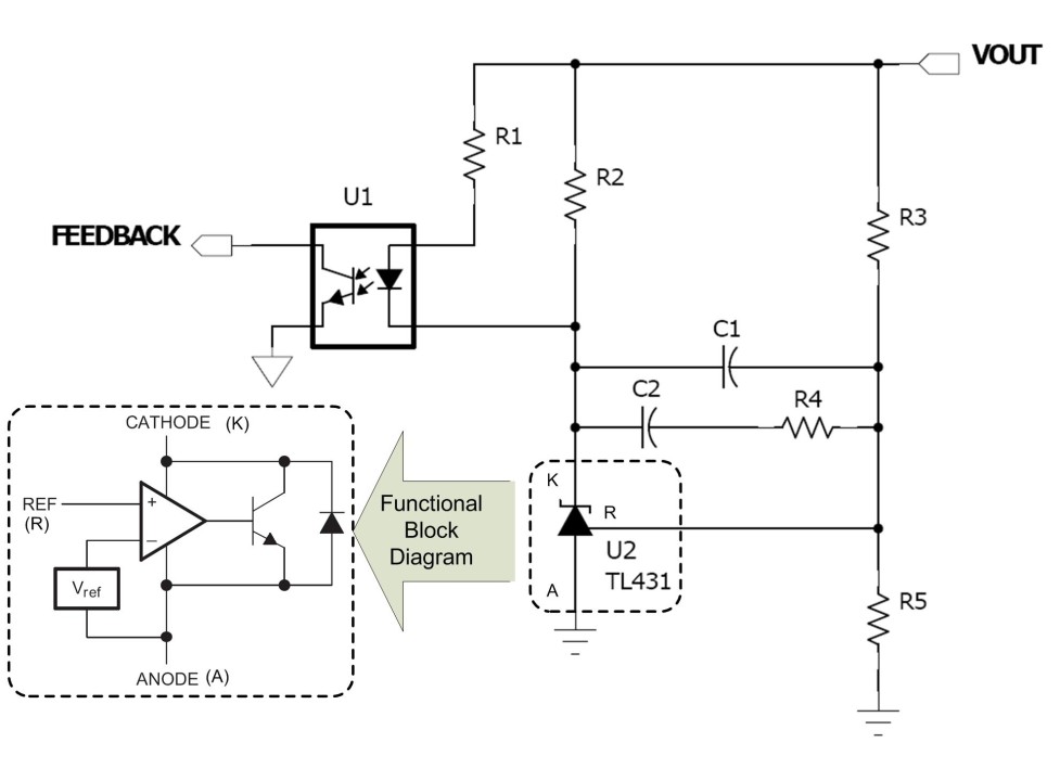
1) Cathode capacitive loading - a serious read of the data sheet reveals there are a lot of values of C that you can't have from the cathode to gnd - just the right amount makes it unstable - a trap for young players who can't be bothered to read.
2) Quiescent current, R2 above must supply enough quiescent current to allow the '431 to work properly, on the standard version this is 400uA - abs min, realistically an experienced engineer will allow more Iq, or buy a different '431 part type that has a reduced need for Iq.
3) Quiescent current - again - that's right - you have to ensure that the Iq being pulled at max load, max Vin and worst case LED aging does not put the opto led too near conduction - where it will reduce o/p power- remember to check this at max ambient for the LED ... this is why you often see a resistor across the LED opto ( and to speed up its turn off )
- at light load / no load, the opto must have enough gain ( CTR ) to hold the pri side controller OFF for the maximum budgeted amount of current you can safely put through the opto-LED.
4) 1st and 2nd order effects, now for the nitty gritty - what happens if you remove a load and the Vout flies up? - 2 effects - 1stly an immediate one, if we assume the cathode volts stay put for a little bit and the Vout flies up - then more current immediately flows though the opto-LED to the cathode - opposing the rise in Vout - a neg feedback effect - then C1 & C2 allow the increased Vout to flow through to the ref pin and the usual op-amp style feedback loop takes effect, hopefully resulting in a new and stable operating point , Vcathode slightly higher, for the new lighter load.
4a) Similarly for a step increased load - two effects - the lowered Vout immediately reduces the current previously flowing in the opto-LED ( Vout to cathode ) providing an immediate neg feedback effect ( Vout bolstered ) - followed by the reset through C1, C2 to a new operating state with a new slightly lowered Vcathode.
5) OK for the real newbie - the '431 generally can't pull it's cathode below the ref voltage ( 2.495 V for the standard version ) - some of the newer types can though - and there are 1.2V ref versions which are great for o/p voltages below 2v5.
6) Beware the variance of Vref for the standard 2% version - and over temp too - make sure your system can tolerate the variance. 1% & 0.5 % types available.
7) Check the worst case power dissipation in the device and for R2 supplying it - make sure you don't exceed the dissipation in the opto LED too for zero load ...
8) Don't overload the cathode point - this will pull down that point and things simply won't work.
Happy designing from the folks at pwrtrnx.com
Hi Colin, if you want to build a true type 2 configuration, C1 is enough for the origin pole and the zero while a capacitor combined with the collector makes the second pole. See https://cbasso.pagesperso-orange.fr/Downloads/PPTs/TL431addedRC.pdf for more details but also https://www.onsemi.com/pub/Collateral/TND381-D.PDF. Cheers, Christophe
Building Advanced test fixture for VITA 68.3
3yNice summary. TL431 needs a parallel capacitor together with series biasing resistor. These forms a LPF and improves PSRR at high frequency, I think. What is your comment on this?
Director - Systems Engineering
3ynice summary. I recall using one a while back and by the time I worked through all the limitations had quite a few additional components. It worked and did its job well. as you say don't overlook the details in the data sheet.