AutoCAD LT and Data Extraction
As indicated previously the AutoCAD command language is primarily biased towards data creation, than data extraction or modification. Thus if we need to extract data from CAD we may need to have access to AutoLISP or COM/.NET. Typically we don't unless we are creating tools which interact with the drawing editor.
I will cover interactive applications in later articles. The primary interest with the first few articles, is that AutoCAD LT is more capable than many give it credit for, and that waiting for extra technology to be added is a potential waste of time, as the needed capability is already there.
So whilst this article makes reference to AutoLISP and COM/.NET technologies and provides code based on such, the technology is not required. The approach is to show that there is potential to remove references to these technologies and make in-house tools independent of a given CAD system. So some of the general ideas presented are equally applicable to other CAD software.
Programming Environments & Languages
As I don't have access to full AutoCAD, most of my sample code will be based on ProgeCAD which is an IntelliCAD based product. AutoLISP and IntelliCAD LISP are reasonably similar, whilst the AutoCAD COM/.NET object model is different to ProgeCAD. This doesn't really matter as the concepts are the same, and if we write our program in a modular and independent manner, it is relatively easy to modify a single module to convert from use of one COM/.NET object model to another.
Since code segments only appear to be displayed when logged onto Linkedin, you can jump to the source code on GitHub:
Whilst MS Excel/VBA code for script generators, and DXF parsers, and abstract data structures can be found on my ExcelCalcs profile.
Alternatives
Also if hobby merges with job, then IntelliCAD products, or DesignCAD or TurboCAD maybe more affordable products for experimenting with COM. If want to experiment with LISP then would typically require an IntelliCAD based product, or ignore CAD and just use common Lisp. Though AutoLISP has features specific to accessing the drawing database, so would need to create some pseudo functions to simulate the behaviour of the AutoLISP system, and possibly some function aliases. This maybe as simple as just providing a default list to process, then when gain access to AutoLISP, put in the real function and test.
I will just refer to the two languages and associated technologies as caddLISP and caddCOM. {Where caddCOM also includes .NET}
Open source CAD alternatives are LibreCAD, FreeCAD and Blender, however they don't have COM interfaces and typically use python or Lua as scripting languages. LibreCAD does support command scripts, but will need slightly different commands than used by AutoCAD: it appears command language is limited to drawing and points. It is also built around DXF files. So LibreCAD community is potentially a good resource for information about processing DXF files.
AutoLISP vs COM/.NET
Also it is to be noted that AutoLISP is also a lot more like the traditional application specific macro and scripting languages, in that the language is unique to the application. Where as Visual Basic for Applications (VBA), and COM introduced a common programming interface across a multitude of applications. There are a lot more applications that support COM/.NET than support LISP, and there are a multitude of available programming languages which support COM/.NET. Therefore for versatility and future proofing adopting COM/.NET is preferable to adopting AutoLISP.
COM server and COM client
It is also to be noted that COM/.NET technology merely provides an application programming interface (API), allowing the application to function as a COM server. There is no requirement for the application to have the VBA editor or other programming environment built into the application. If an application does have VBA editor built-in, then that application can also function as a COM client. Previous versions of DesignCAD mentioned above only acts as a COM server, so if wanted to program in VBA would need something else like MS Excel to act as COM client.
Also for ProgeCAD, the installation of VBA is an additional process, this however is not necessary to use ProgeCAD as a COM server. Personally I prefer to write my VBA code in MS Excel or MS Access, I don't like VBA attached to other kinds of files.
However, as previously for this exercise I will use VBScript, rather than VBA so the code is not attached to anything. As the code is longer I have also used Windows Scripting Host files (.wsf) so that multiple (.vbs) files can be included in the one program. {It should be relatively easy to convert to python or other language}
Are caddLISP and caddCOM Needed?
Now point of focus is that AutoCAD LT does/did not have AutoLISP or COM/.NET automation, and that such is largely not needed, first because it has a command language and second because the command language can be scripted (that is commands batched into a group). If we can perform a task on the command line, then we can speed that task up by placing the commands in a script file.
Other applications do not have a command line interface or command like language. Most other CAD systems are built around point and click, and use icons and menus. So customising, enhancing, and augmenting the capabilities of other CAD systems, typically requires an API and that is frequently in the form of COM/.NET, and typically presents a different approach to getting things done than in the user interface. Where as with a scripted command language, the commands are the same, and the approach to getting things done is similar to the user interface. If can get things done using the command language then do not need an API. Unfortunately Autodesk didn't enhance the command language for advanced scripting, instead it provided a different language. Then again AutoLISP can be considered an enhancement to the command language, as it can be used directly on the command line and does not need to be saved to a file (.lsp).
As AutoLISP development is limited to AutoCAD, it tends to be best suited for interaction with the drawing editor, rather than data extraction.
If we are extracting data then it is generally preferable that we use the other application as the COM client, as that is where the data is wanted and where work is going to continue. So no reason to have VBA editor attached to the CAD system. So use the CAD system as a COM/.NET server from some other application.
If the other application doesn't support acting as a COM client, then rather than build an application in CAD, then would be preferable to write the desired application as a stand alone application, and continue to use CAD in mode of a COM server.
As pointed out in the previous articles, if we create generators for command scripts then we do not require access to any CAD system for our script generator to run, we only need CAD to run the script and that could be carried out by someone else at a future time.
Similarly if we extract data using caddLISP or caddCOM, then we need access to the CADD application to extract the data at the time of the extraction, where as if we use an export file format, then the application using that data does not need access to the CAD system providing the source data. The parsing, sorting and general transformation of the data therefore can be done else where at some future time. Also there is a chance that can find a suitable source code library online to read/write the file format chosen.
If we do not need a two way interaction between the CAD system and some other application, then we do not need caddCOM, if we do not need interaction in the drawing editor then we do not need caddLISP.
So if have a program based on caddCOM to extract data, then it is potentially feasible to rewrite, and remove the reference to the caddCOM object library and to make use of some open file format instead, and remove dependency on a given CAD system. If program is written in caddLISP, then likely possible to readily convert to caddCOM, then convert to open file format. This goes for all CAD systems, avoid creating dependencies. If possible we need to keep the CAD task separate from our task.
If a CAD system doesn't support a given desired export format, then may have to use caddLISP or caddCOM to export the data. However, if it has some open export format, it is likely more useful to create a conversion tool for that file format, and use from the operating system (OS) command line than create something locked to a specific CAD system.
Export Formats
Whilst an export file format may lack certain information, chances are that information is not accessible or available by caddLISP or caddCOM. This likely doesn't have anything to do with something being proprietary and restricted, but more to do with the way the program uses data and generates data, and the relationships between the data format chosen and the data actually available. Such translations can also result in rounding errors.
As an example of an export format consider the ifc format . If I understand this scheme correctly it is not about sharing all information in a building information model (BIM), it is about sharing that information relevant to the interface between two systems. Information which two systems have in common, but which are being designed by two independent specialists. An architect for example likely has little interest in the details about structures or HVAC systems, but they do care if the HVAC ducts have adequate space to avoid interfering with the structure. The spatial information required to visualise such and otherwise check is significantly less than required to design the two systems. They don't need, so why waste resources, lugging this data around?
Data vs Information
Which raises another issue. Data is raw material, it does not become information until it has been transformed and presented in a manner which enables decisions and actions to be taken. Many a contract dispute is because the designers contend they provided the information to the contractor, when all they did was provide useless data.
Why is data in the CAD system?
ok! We have decided to extract the data. But first, why is the data in the CAD system? Part of the objective should be to simplify design, simplify data requirements, and automate documentation of derived design requirements. This should therefore involve pushing data into the CAD system, not extracting it. So if we need to extract data then something has possibly gone wrong with our production processes.
Noting that simple shapes and assemblies can be pushed into the CAD system. Whilst mathematically derived shapes and assemblies can also be pushed into the CAD system. So the data is generally available elsewhere and no need to extract from CAD.
So I see two potential situations. First is that some data is easier to collect graphically. Such as creation of an artistic shape, putting a pin in a map, or collecting information about a room.
The second situation is CAD derived data. This may involve dimensional and geometric set out to determine the location, shape and size of something, and now that we have the something we want information about it. Or may have a mathematically derived system, which only contains some of the desired data, the rest is part of the resultant graphical model.
Both situations are really concerned with derived data, first is more artistic or heuristic in nature and the other more technical. For the second situation there is potential that we can derive the additional information we need by more mathematics. For the first situation there is potential to change the process so not dependent on graphics.
So future wise there is potential to change from a situation of pulling data from CAD to pushing data to CAD for final visualisation. Again it would be preferable to push data to CAD without needing any specific CAD system.
What data can we actually get?
ok! So we need to extract data. So assumption is that the data is there, but that doesn't mean it is available for extraction, or that we are provided with the tools to extract.
So the next part is about the data in the CAD model that caddLISP and caddCOM provide access to, and if this is any better than other means of accessing such data in AutoCAD LT.
Drawing Database Structure
Whilst I don't know the internal data structure of a dwg file, I assume it is similar to a DXF file, and is split into sections which consist of: header, tables, blocks, entities. Each needs to be read/written in order, to ensure that dependent items exist before they are referred to. For example certain commands are dependent on value of system variables, so they have to be set and retrieved before they can be used. Whilst layers may refer to line types, therefore the line types need to be defined before they can be used. Newer CAD systems may have more tables to look at, the concepts are basically the same.
Header
System Variables
As far as I know there is no AutoLISP or COM/.NET function to get a list of system variables and their values. However, CaddLISP has (getvar) and (setvar) to work with known system variables. Similarly the caddCOM drawing document object has a getVariable and setVariable method to work with individual variables.
If was processing a DXF file, then would read system variables and their values, but only the ones which have been defined in the file. For a dwg file, would like to do something similar, list all the variables and their current value, and to do that need a list of the variable names. As there doesn't appear to be a built-in list, need to create a list.
Simple? Create a command script, switch log file on, then use "setvar ? * " to get the list of all variables and current values. Then open the log file, and copy/paste the list of variables into MS Excel, then use "text to columns", to separate the names and values into two columns.
So now that have a list of variable names, it is possible to loop through the worksheet, use caddCOM getVariable to then retrieve the current value of the variable at any given time. Or can set a new value for the variable in the spreadsheet and then use caddCOM setVariable to modify the drawing. The caddCOM approach being adopted because it was better suited to working with other COM applications, such as MS Excel where I wrote the macro and stored the data. Whilst caddLISP may have functions for creating connections to COM objects, my preference is against tools locked in the CAD software.
Now, if I have a list of variables in a spreadsheet I can just as easily loop through the spreadsheet, and create a command script which only lists the values of variables I am interested in, or otherwise sets new values for such variables. Can equally well store the data in an XML file and be independent of Excel. Therefore no need for LISP or COM/.NET, just a suitable programming language (vb.net, C#, python, VBA) to write plain text files.
Tables
To search tables caddLISP has the functions (tblsearch ) and (tblnext ), whilst caddCOM has various collections which can be iterated through. The main tables as a LISP list are: '("ltype" "Layer" "style" "dimstyle" "view" "ucs" "vport" "block" "appid")
Line Types
We can create a command script which lists the line types to a log file, by using:
where "filename" is the name of the line type definition file (.lin). This will basically list two pieces of information the line type name, and a description of the line type. Using caddLISP or caddCOM does not provide much more information, it is really more useful to be working directly with line type files (.lin). The code for this is in ExcelCadTools.vbs, and the document collection is "Linetypes".
A list of line type names is useful to know, for creating command scripts to set line types or rename them. We can use a spreadsheet to map one set of names to another, then generate a script to rename the batch of names.
Layers
The layers can be logged to a file using "-Layer ? *", this can then be copy pasted to a spreadsheet and split into appropriate columns. So whilst I could use caddCOM to write the layers directly to a spreadsheet, using the "Layers" collection, there is no real need to do so.
Using a spreadsheet I can map one set of layer names to another, then generate a script to rename those layers. The cumbersome part is the script will stop if a layer does not exist, therefore need to manually check that the layers exist before creating and running the script.
An alternative approach to using caddCOM is to export to DXF and modify the layers in the DXF file.
But otherwise use a set of command scripts to create layers to be used, and other wise to switch layers on/off, change colours, plotstyles and other layer properites.
However, if do have frequent need to manipulate layers, then caddLISP or caddCOM would be the approach to take rather than command scripts.
Text Styles
Text styles are used by dimension styles, so these need creating and/or extracting before dimension styles. A list can be obtained by logging "-style ? *" to a file, unfortunately this doesn't produce a nice table. So either need to write a program to parse the log file and extract data and present as a table in MS Excel or use caddCOM to get the text styles, using the "TextStyles" collection, and directly write to Excel in table format.
Using a spreadsheet one set of style names can be mapped to another set, and a command script generated to rename the batch of styles. Similarly a command script can be used to modify various properties of the styles.
So caddLISP and caddCOM likely not that useful here.
Dimension Styles
A list of Dimension styles can be obtained by logging "-dimstyle ? *", this provides little more than the names of the styles. The caddCOM collection is "DimensionStyles ".
A spreadsheet can be set up to define various dimension styles, and the values of all the dimension variables for each. Then command scripts generated to create such dimension styles.
As with most tables a spreadsheet can be used to map one set of names to another, and script generated to rename them.
Views
A list of views can be obtained by logging "-view ? *", this provides the name and whether the view is in model space or paper space. The caddCOM collection is "Views ".
Spreadsheets and command script can be used to create, modify and rename.
UCS
A list of named UCS's can be obtained by logging "-ucs ? *", this doesn't provide a neat table, but does provide the name, origin, x-axis, y-axis and z-axis directions. Again CaddCOM can be used to get a table format directly into MS Excel. The caddCOM collection is "UserCoordinateSystems ".
Spreadsheets and command script can be used to create, modify and rename.
ViewPorts
A list of viewports can be obtained by logging "-viewports ?", This provides a table with the names, lower left corner, and upper right corners of each viewport. The caddCOM collection is "Viewports ".
Spreadsheets and command script can be used to create, modify and rename.
Blocks and XRefs
A list of block inserts can be obtained by logging "-insert ? ", this will provide a list of block names and some count statistics at the end. A list of external block references can be obtained by logging "-xref ? ", This will create a table of names, types and file paths. The caddCOM collection is "Blocks", and xrefs have property isXRef=true. {from memory AutoCAD handles this differently}
Spreadsheets and command script can be used to insert and rename.
Registered Applications
As registered applications are typically not supported by AutoCAD LT, I'm not aware of any command to list what they are. Therefore caddLISP and caddCOM are required if want access to this information. The caddCOM collection is "RegisteredApplications ".
Conclusion about Table Data
Whilst access to the tables is important for a routine written in caddLISP or caddCOM, working with such tables, creating the objects in those tables, and renaming items in those tables does not require caddLISP or caddCOM. Whilst these programming tools may provide for creation of more convenient cadd tools than achievable with command scripts, the cost is not necessarily aligned with value: noting that likely going to spend time programming these extra cadd tools.
That is extracting information from the tables has no value in its own right, and we can get the information from the command line. The value of the data in the tables is when we are processing entities.
Entities
It is extracting information about entities where caddLISP and caddCOM becomes most useful. However, our primary consideration is the use of AutoCAD LT, that its 2D and 3D capabilities meet our needs. Furthermore, there is no extended data attached to any entity, the only entities we have are graphical, and the only data attached to them is that associated with display or presentation. So a line is just a line, it isn't a steel beam with section properties, or any other physical object.
Entity Data (other than graphical)
Every entity has to reside on a layer. In caddLISP every entity has a unique "entityname" for the duration of a editing session, during another session its name may change. Every entity has a unique handle, this handle is unique for the life of the drawing, if an entity is deleted that handle is not used again. Therefore entity handles can be used to connect drawing entities to external databases.
Layers have properties, and entities also have properties. These properties can be assigned to an entity directly or bylayer. The basic properties are: colour, line type, line weight. On a drawing visual presentation is used to encode information into a graphical element, and legends and drafting standards are provided to decode.
Therefore line thickness, colour and line type can equally well be used to encode and attach additional information to an entity, and not just by visual presentation but also by name. For example line types can have different names merely to represent some other characteristic of an entity. Line types could have the names of universal beams for example, and therefore a line can now be considered a steel section, and we can extract the size of steel section from its line type property. Or we can have an external program which maps entity colour to some characteristic of a more substantial object than a line.
Layer names are typically used to both group entities together and isolate them. Layer names can be split into multiple fields either on the basis of fixed width, or by some delimiter character. Layer naming standards tend to be based on contract and project management, and tend to be relatively useless for encoding the physical characteristics of a product or system. So its important to differentiate design and modelling from contract document management. It is also important to isolate contract document management practices from production processes (fabrication and construction). If not properly isolated then a useless revision cloud is likely to be cut from an expensive piece of steel.
This is not just a matter of layer mapping and renaming layers. This is separating entities, and grouping entities on to different layer sets. That is entities on layer(1) may be separated into new layers: (A,B,C), whilst layers(2,3) are combined into layer (D). Combined contents of layers is not a problem, separating the contents of a layer is, unless the entities have some distinguishing feature. If all properties are set by layer, then that won't be the case.
So to get additional data from the drawing it has to be put into the drawing and some how encoded, making use of the available properties. {Full AutoCAD has extended entity data}
Groups, Blocks, Xref's, Attributes
Another way to attach additional information to entities is by grouping them or turning them into blocks with attributes. A group provides a means of collecting entities together without them being on the same layer, and then assigning a name to them. The names of groups can be encoded with additional information.
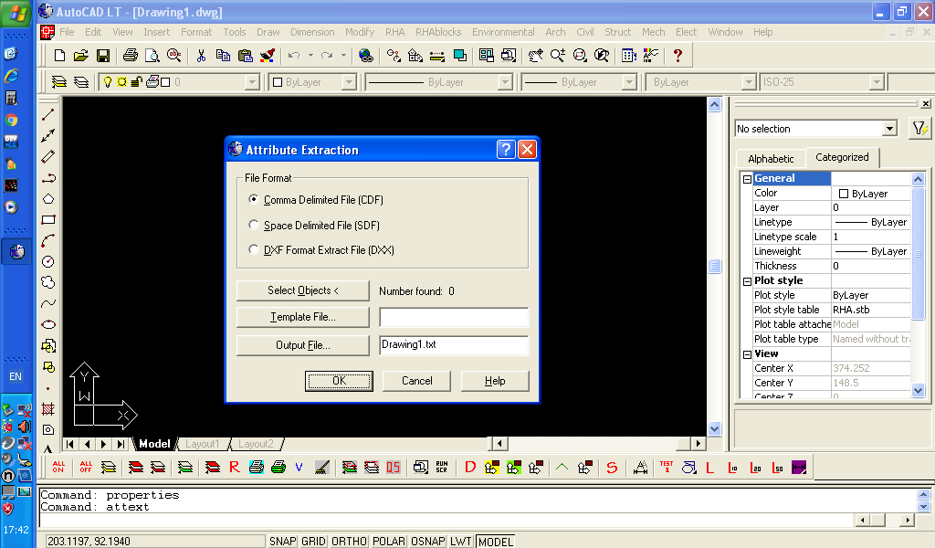
Blocks allow creation of components and subassemblies, and allow combination with attributes. The value of the attributes can be extracted using ATTEXT in AutoCAD LT along with appropriate template, then imported in MS Excel or MS Access or other spreadsheet or database management system (DBMS). {It seems all the articles which say AutoCAD LT cannot extract data are referring to other commands: EATTEXT, or -DATAEXTRACTION, and therefore misleading.}
However turning every graphical entity into a block so that can add extra data would be cumbersome, especially if cannot modify the entity. For example every different length line would have to be a different block definition, if cannot stretch the line. So blocks are useful for subassemblies and assemblies, or as additional markers added afterwards, but otherwise limited value for information. Though some CAD extensions use invisible blocks to store information in a drawing.
Also as far as I'm aware using xref's hinders the use of attributes. However, external references, allow data to be encoded in file names, and other benefits which may come from working with files rather than the contents of a drawing.
However, newer versions of AutoCAD have more advanced editing features for blocks and xrefs. So may gain some additional benefit.
Entities (spatial data)
As using a CADD package our primary concern is with graphical entities which lie in 3D space. Yes everything in AutoCAD LT lies in 3D space, all points have 3 coordinates (x,y,z), we typically draw on the plane with z=0. Architectural floor plans tend to be drawn in the xy-plane with z-axis vertical, whilst structural elevations for export to analysis software are drawn in the xy-plane, with y-axis as vertical. Whilst structural analysis software may allow manipulating the coordinates of the DXF file being imported, its just easier to draw on the xy-plane in the first place as its the default drawing plane.
Most external programs use DXF files as a means of getting the spatial data they need, it is preferable than a direct listing of all entities to a log file. Also AutoCAD LT is limited in other file formats it can export.
The concept that the DXF file is incomplete and doesn't contain all relevant data is likely invalid, as is the possibility that AutoLISP or COM/.NET will provide access to the missing data. If the application programming interface (API) does not provide access to a chunk of data then it is basically not available for use. It is also important to address the difference between creating an entity and the definition of that entity.
Entity Creation vs Definition
For example from a DXF file, it would appear a line is defined by two points. This is not a requirement, an early and simple CAD package called "drafters choice", defined a line by a start point, its length and bearing. The import of a DXF file therefore has to change the definition of the line, and that can introduce rounding error. Rounding error can be important with respect to whether two lines intersect or not.
Structural analysis software typically uses a list of nodes and list of connectivity. A line is defined by two node identifiers, if two lines intersect at the ends then they share nodes. In AutoCAD the two lines have to have exactly the same end point. So to build a list of unique nodes have to compare end points, and decide if going to place a tolerance on acceptance of two different points being considered as the same point. It doesn't make any difference as to whether getting the point data from a DXF file, or from using AutoLISP or COM/.NET.
So if can process a DXF file, then process the DXF rather than upgrading to full AutoCAD just to get AutoLISP or COM/.NET for extracting a bit of data. First of all both these environments make use of DXF codes to extract data. Though COM/.NET possibly is the easier approach to getting data, as DXF codes only required to create selection sets, and not required to access basic data.
DXF vs COM/.NET
It may seem that caddCOM makes life easier than parsing a DXF file. If writing a parser to extract everything and anything found in a DXF file then that maybe the case. However, rather than the complaint of the data not being in the DXF, more likely that the DXF is full of irrelevant garbage, and the task is to sift it out and get to the data wanted.
A DXF file basically comprises of tag-value pairs, with tags on one line and the values following on the next line. So a first stage parser experiment is simply read these tag-value pairs into MS Excel, with the tag in one column and the value in the adjacent column. Depending on version of Excel and size of DXF file, you will likely run out of rows. So next step is to decide what to keep and what to ignore. This part is more complicated as it depends on the structure of the file, and the structure is determined by various tags and their values. For example tag-value pairs which define the start and end of the various sections: header, tables, blocks, entities.
So if we are only interested in graphical entities in the entities section, we just need to find that section, then search that section for the type of entities we are seeking. With a suitable book to guide it isn't that difficult to write such a program. Some times the task is easy as only concerned with a specific tag-value pair and not concerned about its relationship to anything else. So it can be little more than a few lines of code to simply read a file, and grab every instance of a tag-value pair no matter where it is.
If want to change the DXF file rather than extract. Then read from source and write to destination, processing one tag-value pair at a time. If its unknown, ignore and write to destination, if its the thing you are looking for, modify it, then write to destination. So do not have to write code to specifically handle everything in the file.
The problem with the DXF file is that the speed and processing of it can be an interruption to operations. If need to extract the data and use else where, then not so much an interruption, as the lack of interoperability between the two applications is the primary bottle neck to productivity.
However, if objective is to modify data in the drawing file, then an export/import process is likely cumbersome. But this depends on frequency, and position of task in over all operation of things.
For example get foreign drawings: batch export to DXF, then modify, then batch import DXF and create new drawings. Whilst an hindrance, its not so cumbersome. But a need to modify something, several times a day, every day, then export/import of DXF is cumbersome and hindering.
So the benefit of COM/.NET is direct modification of the drawing database, and interacting with the drawing editor. However, if interacting with the drawing editor, then not automating as still have a human operator performing a task. If interacting with the drawing editor, then enhancing and augmenting the editing process. Where editing is modifying that which has already been created.
So the benefit of caddLISP and caddCOM is that can select one or more entities in the drawing editor and get information about those entities, without need to directly search the drawing database. Having selected an entity can also modify that entity.
The other benefit of caddLISP and caddCOM is they provide a simple means to filter the drawing database and just retrieve the entities required, without interacting with the editor.
Filtering Data and/or Editor Interaction
If we just want data extraction we can use any of the data export formats, with DXF being a common option or only option with any given version of AutoCAD LT. We can also use the drawing editor to manually filter data before we export it, so we have a smaller file to process.
We can use command scripts to switch layers on and off, or use select, qselect or filter to select entities based on criteria. Then once we have a selection set we can wblock to another file, and then open and save that file to DXF. Alternatively the DXFOUT command may have options to select entities, its just not so obvious.
If we have to manually create a selection set by picking entities one by one to add to a set, then we need caddLISP or caddCOM, but we also have to ask the question: why do we need to manually select the entities?
AutoLISP: extension to the command Language
As I indicated near the beginning of the article, AutoLISP and other caddLISP can be considered an extension to the main command language, as it can be used from the AutoCAD command line interface (CLI). So we can experiment on the command line. Where as caddCOM is really an external interface, that is it is for an external application looking at the CAD system from outside.
Also caddCOM uses lots of different classes of object to represent graphics objects, where as caddLISP just uses lists. Lisp was added to AutoCAD because it was apparently considered simpler to learn for non-programmers. That simplicity however is questionable. When it was introduced, lists in Lisp were easier to use for variable data, than writing complex pointer based data structures in C. Since then object oriented programming (oop) has become more common place, and creating data structures doesn't require pointers, though may involve references which can be just as irritating. Using COM/.NET typically involves languages which also support oop, such as VBA, vb.net, C#, python. These all typically involve working external to the CAD system.
Using AutoLISP, can either work from the CLI, or create files (.lsp) for longer scripts and load and run these from the CLI. I learnt. AutoLISP in MS DOS days, using an text editor called qedit, or otherwise using Turbo C IDE as an editor, there was no Visual Lisp. There is no Visual Lisp in IntelliCAD products, also if I understand correctly there will be no Visual Lisp in AutoCAD LT, therefore using these products will need to select a suitable external plain text editor like Windows notepad, UltraEdit, or free software such as notepad++. The benefit of programming editors is that they provide syntax highlighting, bracket matching and other features which help with programming, and they can do that for various languages.
AutoLISP: Interrogating Drawing Database from the Command Line
However, we can interrogate the drawing database and do calculations on the command line using AutoLISP, without the need of moving back and forth between an editor. It is also of note that AutoLISP uses prefix notation for its arithmetic, that is the opposite of reverse Polish notation (RPN) used by calculators. So if have extensive algebraic calculations to do, then Lisp may not be the ideal place to do those calculations. All Lisp code is inside round brackets ().
For example to multiply 12 and 5, we would use (* 12 5), to assign a value to a variable we can use (setq x 12), if we want to assign values to x and y, then we can use (setq x 12 y 5). To print the value of a variable we can use (princ x), which only accepts one variable. This is potentially useful for doing calculations on the command line and then using in commands.
To get information about an entity we can use: (setq list1 (entsel)) to select an individual entity, it returns a list with the entity name and the pick point. We can then use (setq en (car list1)) to extract the entity name. Then use (setq ed (entget en)) to get the entity data, which comprises of a list of dotted pairs, where each pair comprises of a DXF code, and its value.
To get a specific dxf code value we can define a function, on the command line as follows: (defun dxf (code elist) (cdr (assoc code elist))). This function takes the dxf code, and the name of the entity data list and extracts the value associated with the first occurrence of the code.
So assuming chose a light weight polyline, which we can check by using (dxf 0 ed) which should return "LWPOLYLINE". We can then get one of its vertices using (dxf 10 ed), which will return a coordinate list similar to (-1094.46 365.720 0.000000). Now traditional polylines used (entnext) to get vertices from additional lists, whilst light weight polylines contain all vertices in the one list. Also of note that in a DXF file, each point is represented by 3 codes, one for each coordinate 10,20,30 for x,y,z. Also there are other number sequences for various other points. In AutoLISP however code 10, returns all 3 coordinates for the point. All vertices use code 10, so each one needs to be extracted.
We can extract the other vertices by reducing the list and grabbing the first occurrence of the code again and again. So first we can create a copy of the entity variable (setq entL ed) with the new entity list (entL) variable we can keep reducing the list and extracting data. If we mess up we can start again by using (setq entL ed).
The following (setq entL (member (assoc 10 entL) entL)) will extract the end of the list starting at the first dxf code that matches 10, and then store this as our new list. Then the following (setq pt (car entL)) will get the first element of the new list which is the vertex point and save it. Then (setq entL (cdr entL)) will drop the first element of the list, so that in the next loop round, we will find the next occurrence of code 10.
So we can execute these 3 commands repeatedly on the command line, by using the command history to keep retrieving them. Or just the first and last command as follows:
So we can step through how the lists are modified. Can also modify the following code to a single line, if not on a single line AutoLISP would flag an error and wait for corrections:
First reset the entity list (setq entL ed), then copy the above to the command line (having adjusted to a single line), it will then automatically run through the list and extract each vertex and store each point in a list. The list can be viewed by using (princ pts). We can use similar procedures to extract the points from the list of points, and to extract coordinates from the coordinate list.
We can search and create a larger selection set by using a filter in the following way.
This sets a value for a layer name (lname), then creates a dotted pair with dxf code 8, the code for layer name, then uses (ssget) with a search filter based on the layer name, which creates a selection set 'ss'. From there we can use (setq en (ssname ss i)) to step through each element of the selection set and get each entities name in turn, using the name we can get the entities data, as shown previous code.
So the basic task is learning about constructing filters to get a suitable selection set, (ssget "X") alone gets everything. Then stepping through the elements of the selection set, getting entity data lists, and breaking lists apart to get at the required data, then doing something with that data. Which as the task is data extraction, would be writing to a file using (write-line).
Once it is determined that the data is accessible from the drawing database, then can move to write all the required Lisp statements in a source code file, with extension .lsp. Then load and use the defined functions as needed.
For a non-programmer its simple right!
Introduction to caddCOM
To use caddCOM we need to choose a programming language, for my examples on Github I have chosen VBscript and MS Excel/VBA.
The first requirement is to create an object to reference the CAD system, since I am using IntelliCAD I do that as follows:
Which is otherwise wrapped in error trapping. Once we have done this then we can create objects to reference the drawing document and the drawing entities in model space.
We can then loop through the entity data in the following manner and write to an MS Excel worksheet.
The EntityType property can be used to decide what to do with an entity and extract additional information relevant to that entity. If using VBA and intellisense, then can set 'ent' to a specific object type (class), and see what additional properties are available to access. Or can use the VBA object browser to see properties of objects, if provided a reference to the type library in VBA. (eg. tools/reference).
Creating selection sets is similar to caddLISP, except arrays are used instead of lists. There is one array for group codes and another for the values.
The code is looking for text entities on the given layer. It is selecting from all entities, but could be limited to a window defined by two points, the two points have been defined to the extents of the drawing. Two sets of variables used because the method parameters require variables of type variant, and the assignment of values wasn't to variants. Once got the selection set, then can loop through the entities in the selection set, in similar manner to the previous piece of code.
This code can be placed in any suitable application which supports the VBA editor, preferably the application we are trying to get the data into. Or it can stand independent of other applications. The example I provided on Github, uses VBScript, and creates IntelliCAD object and MS Excel Object, and gets data from CAD and places it in several worksheets of a new workbook. It also shows how to loop through each point in the coordinates collection of a lwpolyline.
Conclusion
So now have the basic building blocks for extracting data from CAD using either caddLISP or caddCOM. An application is most likely going to be doing something prior to grabbing the data, then it will be doing something after it has grabbed the data, so grabbing the data is only a portion of the over all program.
Therefore if written to make use of caddCOM, it is most likely adaptable to using other CAD systems COM/.NET objects. But if written in a language compatible with caddCOM, it would be even more versatile program if it extracted data from an open format data file, available from a multitude of CAD systems. If use an appropriate opensource class library then no more complicated than using the caddCOM object model. Also if not looking to extract all data, the parser can be written specific for the task and be much simpler, than using a full blown parser library.
PS:
Whilst Autodesk website indicates AutoLISP will be included with AutoCad LT 2024, its functionality will be limited due to the limitations of Autocad LT. Also the implementation of ActiveX will not allow AutoCAD LT to operate as an equivalent COM/.NET server but the object model will be available to AutoLISP, which in some situations can simplify accessing data without need to use dxf codes or manipulate lists.
However, given that a lot of tools are written in AutoLISP because the authors didn't know any better or because they could, it isn't really cause for celebration. When I started this series of articles it was on an assumption that AutoCAD LT didn't have AutoLISP or ActiveX (COM/.NET), then whilst writing I discovered it was getting such technology: which was disappointing.
Given the subscription pricing model it likely means a few businesses using full AutoCAD will change over to AutoCAD LT and continue using their in-house Lisp routines. Some people may change from IntelliCAD based products to AutoCAD LT, but given perpetual type licence and move to to annual subscription, that is unlikely. Also people unlikely to change because full AutoCAD and IntelliCAD have built-in features not available in AutoCAD LT.
Given AutoLISP is not required for automated drawing creation, and it is not required for data extraction, its primary benefit lies with interaction with the editor, but is it required here? Whilst AutoLISP may make it easier to do certain things it doesn't mean it is required to do those things. If an AutoLISP tool is going to be placed in a menu, or toolbar button, does that functionality require AutoLISP? It maybe harder to workout using DIESEL, and slightly clumsy using macro pauses, but if feasible it maybe adequate and acceptable.
Whilst if proposing to write a more fully fledged and extensive application, why is it being built on AutoCAD, why is it being written in AutoLISP? If an application is not interacting with the drawing editor then it does not need AutoLISP, if it doesn't need AutoLISP then it also likely doesn't need AutoCAD. So better to avoid making the application depend on a single CAD package.
Also if need an extensive application to interact with the drawing editor, then these days AutoCAD is likely the wrong package to be working with. More importantly if write an extensive application, it is likely only a few steps away from becoming independent of a given CAD system, and having its own editing environment specific to its task. The more that has to be written the more likely starting with the wrong application as the foundational building block of your desired application.
References:
C W Sharp and W W Hamm (1989),"AutoCAD Advanced Techniques", Que
J. Smith and R. Gesner (1989), "Inside AutoLISP: Using AutoLISP to customise AutoCAD", New Riders Publishing
George Omura (1990), "The ABC's of AutoLISP", Sybex
Dennis N Jump (1989), "AutoCAD Programming", TAB Professional and Reference Books