
TL431 Lithium BMS module is a Battery management system based on integrated circuit TL431 for lithium cell overcharging prottection. This single module can monitor the 1S cell at a maximum current of 1 Amp by adjusting the target DC voltage from 3.75V to 5V. It can be suitable for lithium-ion, lithium-polymer, and 4V acid batteries.
This custom BMS module PCB has been designed by me. You can order the same or gerber file download from PCBWay Shared Projects.
TL431 Lithium BMS Module Specifications
The quick specifications of this cell prottection module is given below:
- Type: BMS
- Module: Overcharging Prottection
- Operating Voltage: DC 3.75 ~ 5V
- Operating Current: 1A Max.
- Monitoring Accuracy: 98%
- Board Dimantions (L x W): 30mm x 25mm
- Weight: 4gm
TL431 Lithium BMS Module Circuit Diagram
Schematic of the tl431 lithium b.m.s. module circuit for over-charging protection is shown below.
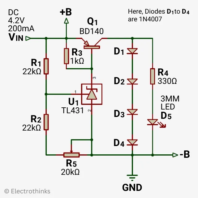
Components are used in the circuit - U1: TL431 IC, Q1: BD140 PNP Transistor, R1 & R2: 22kΩ Resistor, R3: 1kΩ Resistor, R4: 330Ω Resistor, R5: 20kΩ Veriable Resistor, D1-4: 1N4007 Diode, and D5: 3mm LED.
The working principle of this Battery Management System (BMS) module circuit is simple. TL431 precision shunt voltage regulator intregrated circuit provide a stable reference voltage to the transistor (Q1) by adjusting the variable resistor (R5).
As we know, a 3.7V lithium cell's charging voltage is typically 4.2V. When the cell reaches the target charging voltage, the TL431 circuit activates the transistor (Q1) and starts bypassing the charging voltage through diodes (D1-4). Consequently, the excess voltage is converted into heat through the transistor, diodes, and LED (D5) turns ON. Thus, this BMS protects the cell from overcharging.
How to Interface TL431 Lithium BMS Module with Charger
|
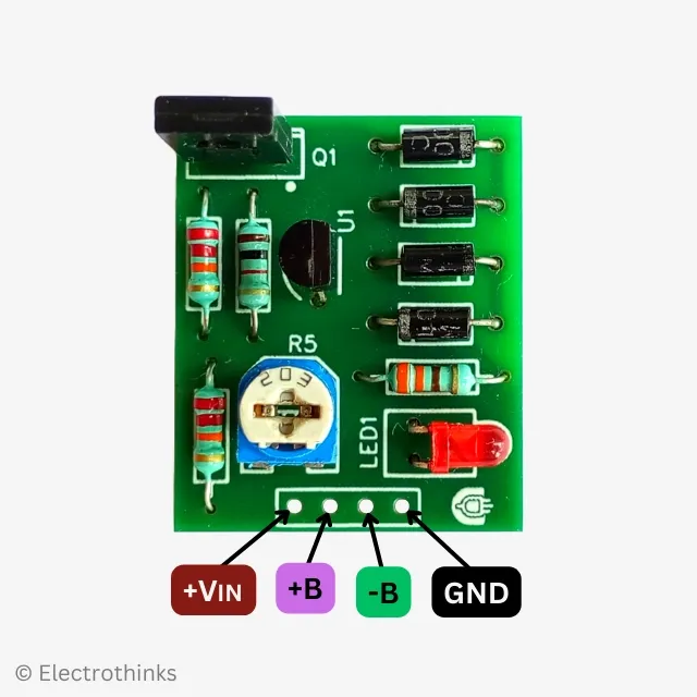
The module has 4 connecting points those are -
|
First, you connect the input voltage (+VIN) and GND terminals of the BMS module to the output voltage (+VOUT) and GND from a charger, respectively. Next, connect the multimeter probes to (+B & -B) terminals, and set the target charging voltage by the variable resistor. Then finally, connect the terminal (+B) to the positive terminal of the cell and the terminal (+B) to the negative terminal.
Additionally, if you want to charge more than one cell at the same time, this module allows monitoring up to 5S cells. Below is the connection diagram for 1S, 2S, 3S, 4S, and 5S cells.
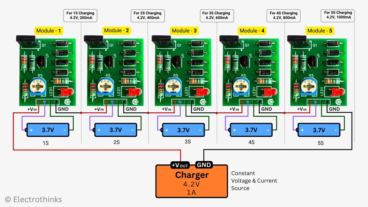
Please, remember that the charger output voltage should be regulated with a constant current, which should be set at a rate of 20-35% of the cells' capacity.


No comments
If you have any doubts or questions, please let me know. Don't add links as it goes to spam. Share your valuable feedback. Thanks