
Most of the electronics circuit used a Zener diode as voltage regulator to provide a precision voltage reference. The intregrated circuit TL431 acts almost like a Zener diode except for that the voltage rating of this IC is programmable.
But the question arises do you know how does the IC TL431 works, what inside it, and TL431 circuit diagram? Let's learn about TL431 and Circuit diagram with working explanation.
What is a TL431?
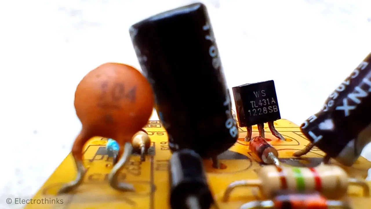
A TL431 is a tree-terminal precision shunt voltage regulator intregrated circuit which can programmable with the use of an external voltage divider. It can regulate voltage ranging from 2.5 to 36 V, at currents up 100 mA to provide a stable reference voltage to other components in the circuit. A Zener diode can be used as an alternative to the TL431 IC.
Features of TL431 IC
The quick technical specifications of the TL431 are as follows:
- Type: Programmable Zener Diode
- Adjustable Output Voltage: DC 2.5 V to 36 V
- Output Impedance: 0.22 Ohm
- Cathode Voltage: 2.5 V to 37 V
- Cathode Voltage Tolerance: ±4%
- Cathode Current: 1 mA to 100 mA
- Reference Input Current: 0.05 mA to 10 mA
- Operating Temprature: -40°C to 150°C
IC TL431 Pinout

The IC has 3 pins those are -
| Pin No. | Pin Name | Description |
|---|---|---|
| 1 | Reference | This pin sets the voltage rating of the TL431 IC. |
| 2 | Anode | Current always Enters through Anode. |
| 3 | Cathode | Current always Exits through Cathode. |
TL431 Precision Voltage Reference Circuit Diagram
The schematic of tl431 shunt voltage regulator circuit is shown below.

Working principle of TL431 Shunt Voltage Regulator Circuit
The working principle of the TL431 circuit is simple. First, the circuit limits the input current by employing a current limiting resistor. Next, it generates a reference voltage through a voltage divider circuit. The integrated circuit TL431 internally compares the input reference voltage and provides a precise voltage reference as programmed.
Current Limiting Resistor
As we know, the IC TL431 is capable of sinking a current of up to 100mA. Therefore, a resistor, denoted as RX in the circuit diagram, is used to reduce the current to the required level.
The value of this series resistor can be calculated using Ohm's Law,
RX = (VIN - Vf) / I ...(i)
Where VIN represents the input source voltage, Vf represents the forward voltage, and I represents the desired current allowed in the circuit.
External Voltage Divider Circuit
It consists of two resistors (R1 & R2) connected in series, with the output voltage taken from the connection point between them. This output voltage is required for the TL431 as a reference input voltage.
The value of the two resistors can be calculated using the voltage divider rule,
VR2 = VIN x R2 / (R1 + R2) ...(ii)
Where R1 & R2 represents the voltage divider resistors, VR2 represents the voltage accrose the resistor R2, and VIN represents the input voltage from RX.
Intregrated Circuit TL431

According to the internal circuit diagram of TL431, it consists of three main components:
- Precision Reference Voltage Source (VREF): The TL431 has an internal voltage reference source that provides a stable and precise reference voltage (VREF) of 2.5 V. This reference voltage is the target voltage that the IC strives to maintain at its output terminal.
- Comparator: It compares the input reference voltage from the external voltage divider circuit to the VREF. The input voltage is connected to the non-inverting input of the comparator, while the VREF is connected to the inverting input. The comparator continuously monitors the input voltage and adjusts the output accordingly.
- Transistor: An NPN transistor is used to control the current flow to the load. When the input reference voltage exceeds the VREF, the comparator generates a control signal to regulate the transistor. The transistor either allows current to flow to the load or shunts it away, depending on the voltage difference between the input reference and VREF. This action ensures that the output voltage remains stable and closely matches the VREF.
The programable precision voltage reference can be calculated using this formula,
VOUT = VREF x (1 + R1 / R2) ...(iii)
Where VOUT represents the output voltage of the TL431 circuit, R1 & R2 represents the voltage divider resistors, and VREF represents the internal reference voltage (2.5 V) of the IC.
Program TL431 Circuit for Precision Voltage Reference
Suppose we want to program a TL431 circuit for a precision 4.2V reference. We need to determine the total current flowing through the circuit.
Thus, there are three paths for the current to follow:
- Load: Let's assume our load consumes 80mA.
- TL431 IC: The minimum current flowing through a TL431 is around 0.5mA, but we'll select it as 1mA.
- Voltage Divider: The IC's minimum input reference voltage is 0.05mA. Therefore, we need to allow the minimum current possible.
TL431 Circuit Calculations
The IC has an internal reference voltage of about 2.5V, so the two resistors in the voltage divider can be calculated using formula (ii). Which is,
VR2 = VIN x R2 / (R1 + R2)
Or, 2.5V = 4.2V x R2 / (R1 + R2)
Or, R1 + R2 = 4.2 x R2 / 2.5
Or, R1 + R2 = 1.68 x R2
Or, R1 = 0.68 x R2
Therefore, if we choose an R2 value of 10kΩ, R1 will be 6.8kΩ. The current across the two resistors for 4.2V is,
I = VIN / (R1 + R2)
Or, I = 4.2 / (6.8 + 10)
Or, I = 4.2 / 16.8
Or, I = 0.25 mA
Thus, the total current flowing through the TL431 circuit is 81.25 mA, and the series current limiting resistor should not allow a current higher than 81.25 mA to pass through it.
If we want the circuit to operate with a maximum input voltage of DC 12V, we can calculate the required series resistance using formula (i). Which is,
RX = (VIN - Vf) / I
Or, RX = (12 - 4.2) / 81.25
Or, RX = 96Ω (let's round it to 100Ω).
Now, simply put the values in the formula (iii). Which is,
VOUT = VREF (1 + R1 / R2)
Or, VOUT = 2.5 (1 + 6.8 / 10)
Or, VOUT = 4.2V
Let's compare the test output voltage with the resistor values calculated above and verify if the output matches!
TL431 Circuit Assambled on Breadboard
I simply arranged the components and assembled the precision voltage reference TL431 circuit on a breadboard according to the schematic.

Testing & Demo - TL431 Circuit
To test the circuit, I supplied a 12V DC source and checked the output voltage using a digital multimeter, which displayed a voltage of 4.2V. Hence, the measured output voltage of the TL431 circuit is identical to our calculated output result.


No comments
If you have any doubts or questions, please let me know. Don't add links as it goes to spam. Share your valuable feedback. Thanks