- Older engines with electronic fuel injection (and many high-performance or turbocharged engines) use speed density tuning, which accesses MAP sensor data.
- Newer vehicles, starting in the mid-2000s, mostly use MAF tuning.
There are other factors to consider.
- Many engines have both MAP and MAF sensors.
- The MAP is used for secondary adjustment or backup if the MAF fails.
- Without a functional MAP sensor, your engine control module (ECM) can’t efficiently manage the engine’s operation, leading to poor running conditions and increased fuel consumption.
- Engines that use MAP sensors instead of MAF sensors require data from an intake air temperature (IAT) sensor and the engine coolant temperature signal to determine the airflow mass.
Under Pressure
Unlike MAF sensors that measure air flow, MAP sensors measure pressure. The MAP sensors are typically mounted in a port to the intake manifold.
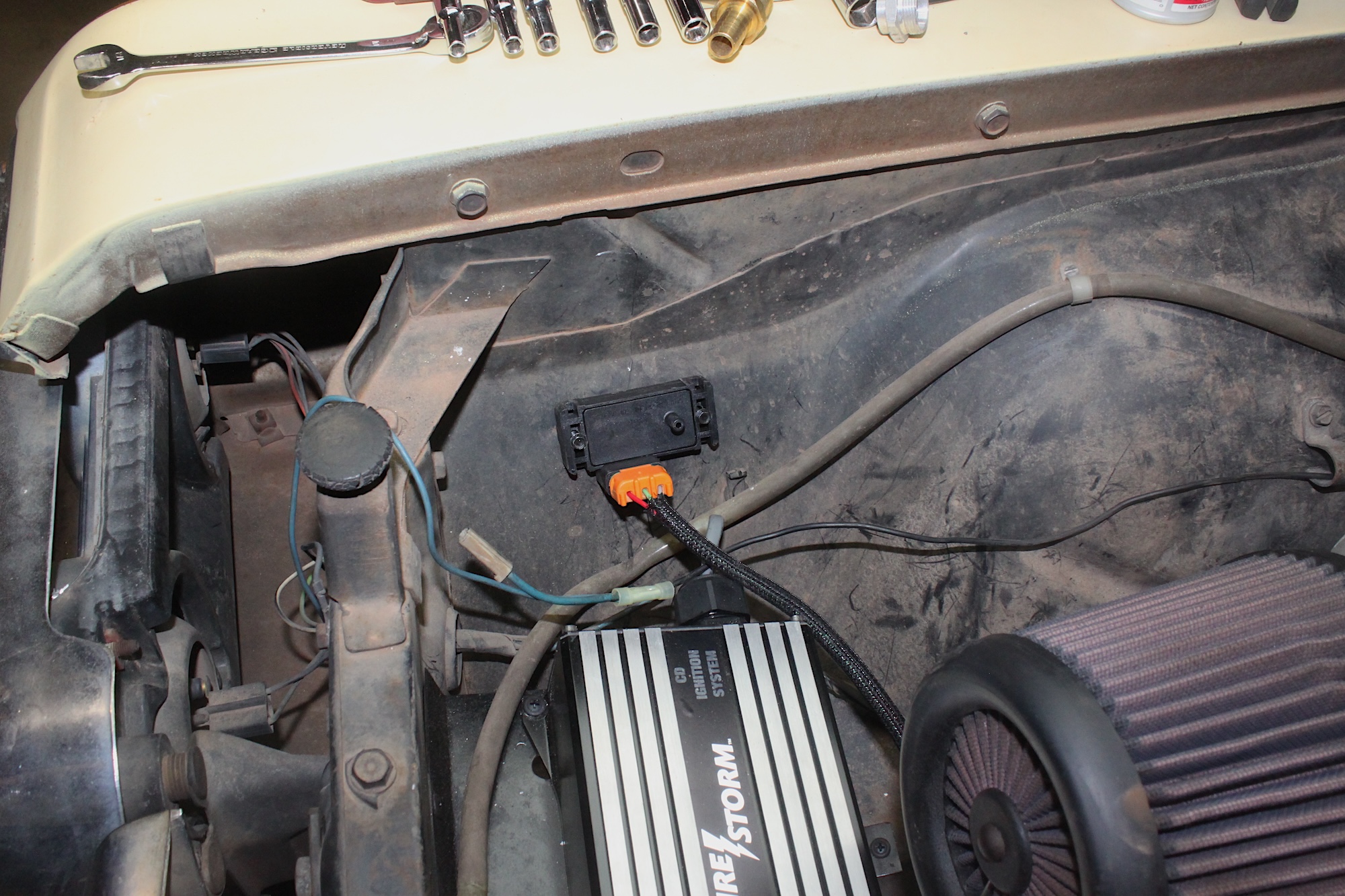
This remote-mount MAP sensor is installed in custom turbocharged vehicles. The hose barb nipple gets connected to a vacuum hose, which is connected to the intake.
For some turbocharged engines, the MAP is located in the air intake tubing before the turbo (pre-boost), so the boost doesn’t affect it.
The sensor uses a sealed reference chamber (vacuum or pressure) calibrated for the specific application. A pressure chip pushes against the sealed chamber, changing the resistance to the supplied voltage. The ECM uses this signal to determine the correct tuning operations to send to the engine.
Map sensors read the barometric pressure in the atmosphere when the key is turned. That provides data to the engine about the outside world. Weather, temperature, elevation, and other ambient factors affect an engine’s operation.
After you start the engine, the sensor reads the pressures in the intake. An engine pulls vacuum at idle and light throttle, then goes back to atmospheric or into pressure, as with supercharged and turbocharged engines.
Shop now for MAP sensorsSigns of Failure
Because the MAP sensor is inside the intake, it is exposed to air, dirt, fuel, and other contaminants that eventually clog it up. Diesel engines are prone to clogged MAP sensors because of soot that enters the intake.
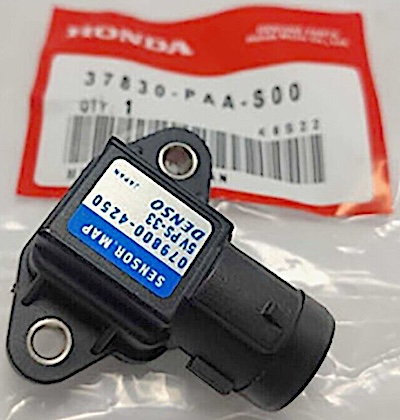
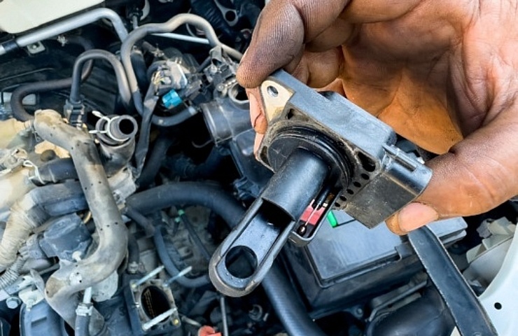
1992-2013 OEM Honda/Denso MAP sensor
When the MAP gets clogged or fails, you will notice a few things about your engine’s operation.
Rich or lean conditions – The engine may run overly rich or lean. Your engine will stall, have poor fuel economy, rough idle, hesitate, or even backfire through the intake (not exhaust)
Detonation/misfire – This is when a cylinder ignites at the wrong time. You will hear a pinging sound or high-pitched rattle.
Check engine light – The check engine light will come on when the MAP is clogged or dying. Check your codes with a scan tool. Standard AP codes are P0068-69, P0105-09, and 1106-07.
Testing a MAP Sensor
The MAP sensor is an electronic device. Check the plugs and wires for any breaks, damage, or corrosion that could cause an issue with the signal.
It would help if you had a digital multimeter to test your MAP. Check with your service manual for the detailed specs your MAP sensor should read and which wire is which. Verify the vehicle reference voltage is correct at the plug. The battery must be in good condition and fully charged.
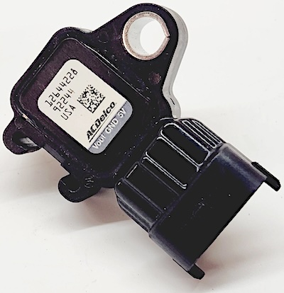
OEM GM/ACDelco MAP sensor
- Your sensor should have three wires: signal, ground, and a 5-volt reference.
- Turn on the ignition switch to the “run” position; do not start.
- Set the meter to 20v DC or DC “Auto Range.”
- Attach the negative probe to the negative battery terminal or a good engine ground.
- Back probe each wire (push the probe into the backside of the terminal) to verify the voltage. You should be sure you are making contact with the terminal and not getting stuck on the plastic. You can pierce the wire jacket if necessary. Remember to tape the wire when done if you go this route. Back probing is preferred.
- The 5v reference wire should read 4.5-5v.
- The ground wire should read 0. (check this terminal for continuity to ground as well)
- The signal wire should read .5-1.5 volts for non-boosted engines, but turbo/supercharged engines use three and 4-bar MAP sensors, which will read differently at the base atmosphere.
- Start the engine. Retest the signal wire. The voltage should change as the engine idles.
Cleaning the MAP Sensor
Cleaning a MAP sensor is easy, but you need an MAF sensor cleaner.
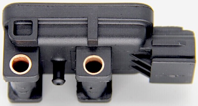
OEM Dodge/Ram/Jeep/Bosch MAP sensor
- Remove the sensor from the engine. Most of the time, these pop out of a bung in the intake or air tube. Some sensors use a vacuum line that runs from the intake to the sensor. These are not exposed to the contaminants inside the intake, so they don’t get as dirty.
- Spray all sensor parts, including the terminals, with the MAF cleaner.
- Wipe with a clean towel.
- Repeat as needed. Diesel MAP sensors get very clogged. Cleaning may take some effort.
- Reinstall the engine and connect the terminal plug. Test run the engine to verify function.
How To Replace a MAP Sensor
There are many types of MAP sensors, but most fall into one of two categories: intake mount and remote mount. Intake mount sensors snap into a bung on the intake. There may be a screw, bolt, or tab holding it in place, or it may twist-lock. Most are friction fit, and you pull it out.
Check your repair manual for details.
Remote-mounted sensors are not in the intake. They are mounted elsewhere, typically on a bracket on the intake/engine or the firewall near the intake. They use a small hose or pipe to get the readings from the intake.
These do not get dirty, as the line acts as a buffer. Remote-mount sensors are typically secured with screws, bolts, or a friction tab.
- Locate your MAP and determine the type.
- Disconnect the terminal plug.
- Remove any screws, bolts, or locking tabs to free the sensor.
- Remove the sensor from the vehicle.
- Install the new sensor in reverse steps compared to removal.
- Your vehicle may require any new MAP sensor to be “learned” to the ECM. This is typically a simple process and can be found in your owner’s or repair manual. Some engines require a diagnostic scan tool to relearn the MAP sensor.
Pro tip: Some vehicles lose the MAP programming when the battery is low or replaced. If you recently replaced the battery and have a MAP sensor code, try relearning the sensor before testing or replacing it. This isn’t common, but it happens.
Airflow information is critical to any ECM to tune the engine properly. All tuning begins with MAP sensor readings. That’s why keeping your MAP in top condition is crucial to automotive maintenance.
Shop now for MAP sensors