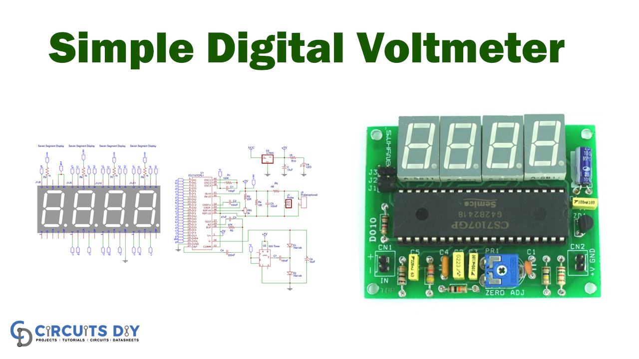
In this tutorial, we are making a “Digital Voltmeter without utilizing any microcontroller.” Instead of microcontrollers, we utilize a well-known IC for voltage estimation to be specific “ICL7107/CS7107.” i.e., ICL7107,
After the end of this article, we will collectively build a digital voltmeter circuit that will ultimately make it cost-effective and precise. However, an ICL7107 is a 3.5 digit ADC converter analog to digital, which devours low power. The IC has an internal circuit for driving four “seven-segment displays” to show that it is under measurement voltage. It likewise has a timer circuit and a reference voltage source.
Hardware Component
The following components are required to make Digital Voltmeter Circuit
| S.no | Component | Value | Qty |
|---|---|---|---|
| 1. | IC | LM555, ICL7107/CS7107, LM7805 | 1, 1, 1 |
| 2. | Seven Segments Display | – | 4 |
| 3. | PCB | – | 1 |
| 4. | Terminal Block | 2 pin | 2 |
| 5. | Resistor | 1K, 10K, 47K, 22K, 120K, 5K Var | 1, 1, 1, 1, 1, 1 |
| 6. | Capacitor | 10uF, 47nF, 220nF, 100nF, 100pF | 2, 1, 1, 3, 1 |
| 7. | Power Supply | 9v/12v | 1 |
| 8. | LED | – | 1 |
| 9. | Berg sticks | 2 | 1 |
| 10. | IC base | 40 Pin, 8 Pin | 1 |
| 11. | Probe or wire | – | 1 |
| 12. | Diode | 1N4148 | 1 |
LM555 Pinout
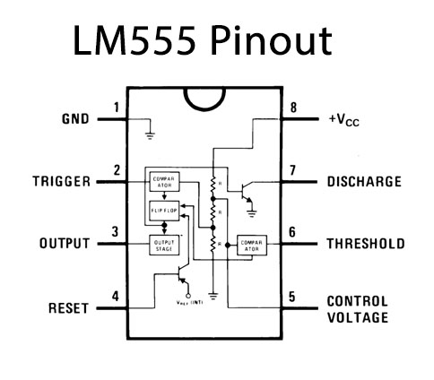
For a detailed description of pinout, dimension features, and specifications download the datasheet of LM555
LM7805 Pinout
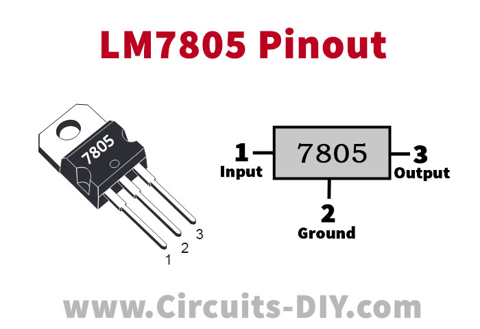
For a detailed description of pinout, dimension features, and specifications download the datasheet of LM7805
L7107/CS7107 Pinout
For a detailed description of pinout, dimension features, and specifications download the datasheet of L7107
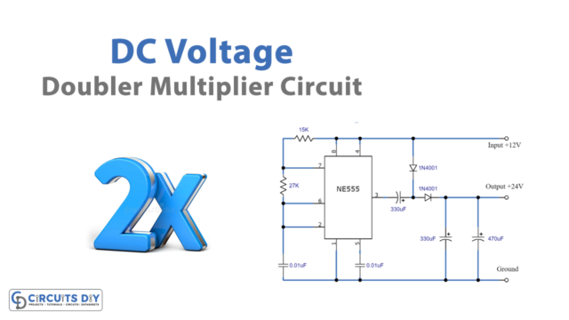
Digital Voltmeter Circuit
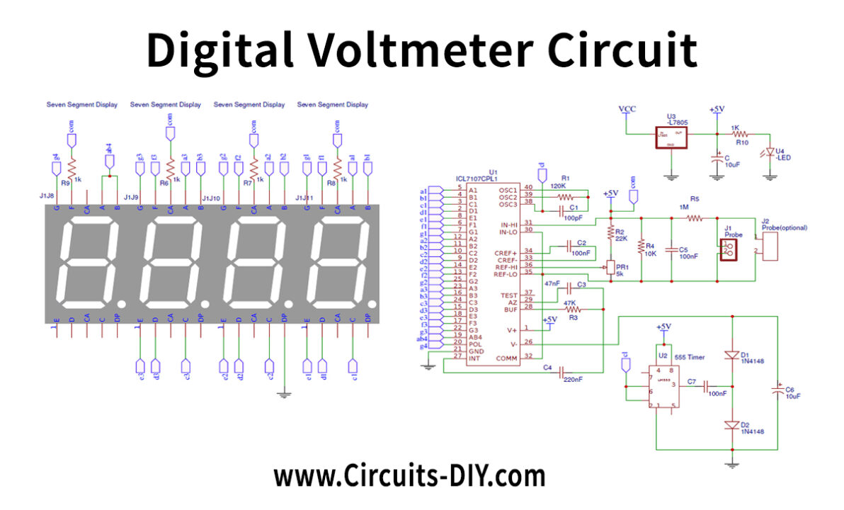
Working Explanation
Working with this Digital Voltmeter Circuit is exceptionally straightforward. ADC inside the IC is incorporating a converter or Dual sort Analog to a digital converter. Inside ADC of this IC peruses the voltage that is estimated and contrasts it with an internal reference voltage and changes over that into the digital proportional. At that point, this digital proportionate is decoded for Seven Segment Displays by driver circuit inside ICL7107 and afterward showed more than Four seven segments LED display.
Here resistor R1 and capacitor C1 are utilized to set the frequency of the inward timer of ICL7107. Capacitor C2 channels the vacillations in inward reference voltage and gives stable perusing on seven-segment displays. However, R5 is desired for controlling the range of the voltmeter. (R5=1K for 0-20V range and 10K for 0-200V range). RV1 is a potentiometer that might be utilized to adjust the voltmeter’s voltage or set as the reference voltage for interior ADC.
This circuit incorporates 4 Common Anode Seven Segment LED Displays with a negative voltage pointer. This circuit ought to be worked at 5V voltage flexibly, that is why we have utilized a 7805 voltage controller IC to supply 5v to the circuit just as for forestalling the harm of ICL7107.
Applications and Uses
- Use to measure the potential difference between two voltage terminals.