
 In this article, I will do a walk-through of a logical network diagram. As I also said in the Physical Diagram article: I prefer to use the term “logical” instead of “L3” because it is more easily understood by somebody unfamiliar with the OSI model. It also removes the assumption (made by many non-technical people) that “L1” and “L3” diagrams are incomplete without a “L2” diagram. So I just call them “Physical” and “Logical” to avoid the confusion.
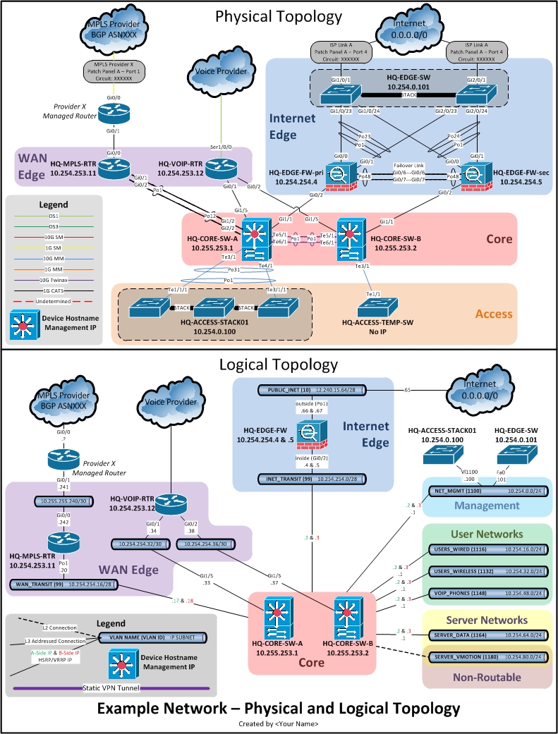
You can download this article’s template file using the link to the right.
Logical Diagram Stencils
Stencils in a logical diagram should be, obviously, logical representations of the network nodes. Keeping that in mind, I propose that it doesn’t make sense to use a physical network device stencil, which is essentially a picture of the actual device (with ports, fans, rack ears…), in a logical diagram. I prefer, instead, to use generic icons which represent different types on network devices in a network.
My favorite resource for generic topology icons is Cisco. You can download a library here or visit the Network Topology Icons Homepage. I am also including the most common icons in the template linked at the top of the page.
Subnets
Subnets are the cornerstone of a logical network diagram. They represent an IP network where nodes can hold L3 addresses and communicate via IP.
 There are three important pieces of information to hold in a subnet object: VLAN Name, VLAN ID, and assigned IP block in CIDR format. The VLAN name and ID information assume that the subnet is contained within a VLAN on a switch. When this is not the case (like with a point-to-point link between two routers), omit the VLAN ID and name and include only the subnet. These different pieces of information are distinguished on the subnet with different font types.
Connectors
Connectors in a logical diagram connect a device to a subnet and represent a layer-3 (or sometimes layer-2) presence on the subnet. There is no need in this diagram for different colored connectors, so always use a solid black pattern. The exception to this rule is non-routable subnets (like heartbeat or vMotion), where the VLAN exists on a switch, but the switch has no layer-3 presence; in this case, use a dot or dash patterned connector.
Each connector is labeled with its IP information specific to that VLAN. Here are a couple of rules I typically follow when labeling the connectors:
- If the connector is connecting a layer-3 switch to a VLAN which resides on it (with a VLAN name and ID), then simply use the last octet (or how ever many you need to specify the address with the mask in mind) and it can be assumed that that connector represents an SVI on the layer-3 switch
- If a FHRP (HSRP, VRRP, GLBP, etc) is present on the subnet, list the physical addresses of the nodes with different colors (see the section about the Legend) along with the FHRP VIP in black
- Whenever possible, list the name (or an abbreviated name) of the interface which has the logical connection to the subnet (A Cisco router might be something like “Gi0/0”). It may also be appropriate to list the interface alias when the device uses one (like a firewall with named interfaces).
- When multiple connectors are required to connect a single subnet to multiple devices which are grouped together, you can use one connector and connect it to the grouping box. In this case, define multiple IPs on the connector for the different devices.
***NOTE***
In cases when a layer-3 switch holds VLANs where it has no layer-3 presence (like when a public internet block is switched on a L3 switch, and not routed), but other devices in the diagram do hold a layer-3 presence on that subnet: attach the subnet to that switch with a dash connector and hide the connector with a layer so it doesn’t obstruct the rest of the diagram. You can find a quick tutorial on Visio layers here. I have included an example of this in the template.
Grouping Boxes
 One of the first things you may notice on the template document are the colored background grouping boxes labeled “Internet Edge”, “WAN Edge”, etc. These boxes are used to group similar devices (or subnets) into a category or named section of the network when they have related purposes.
Grouping boxes can be used to take a complex topology, with many devices interconnected in confusing ways, and turn it into a simpler and more hierarchical topology; with each device detailed and defined, but serving a role in the larger function of the group.
Device Labeling
Each node (switch, router, firewall, etc) should optimally be labeled with a hostname, and a management IP address. When possible, list a loopback address that has less dependence on the physical interfaces of the device.
 The obvious exceptions to this rule are things like devices managed by somebody else (where the hostname or management IP are unknown). In the case where there is an active device which is managed by somebody else (ie: CPE router), label it with a non-bold, italicized font (labels for standard devices are bold and non-italicized).
***NOTE***
In a case where you are diagramming a device which has multiple active VRFs: add the different VRFs as different device icons. Label the device icons with the same hostname and management IP, but add a third line with the name of the VRF. You can move around and treat the VRF device icons as separate devices in the network because, logically, they are different devices.
The Legend
 The legend is a very important part of your logical network diagram. It informs the reader on how to interpret the different pieces of information in the drawing. It also sets the ground rules for you to follow when diagramming the network.
I have included my standard logical diagram legend in the template linked at the top of the page. It has the most commonly used connector types defined, but can always be modified as needed.
Create/Maintain
Up to this point, this article has described the different components of a logical diagram and their meanings. Next we will cover how to create and maintain a logical network diagram. It is assumed at this point that you will be able to use Visio to diagram the logical network topology, using the methods described above once you have the connectivity information. This section will describe the steps to take to get that information.
***NOTE***
Remember that a logical network diagram only records the nodes in the network which have an in-band, layer-3 presence. There is no need to include devices like layer-2 switches, bridges, etc.
Connected Networks
The best way to start on a new logical diagram, in an unknown network, is by logging into a “core” device, or a device which has many connected subnets and has routes to remote networks (either static or dynamic).
Begin by listing out all connected subnets on the device (also list out any VLAN information associated with these subnets). First, add this device to the drawing and label it with the hostname and management IP address. Then translate these subnets and VLAN info into subnet objects in the drawing. As you create each subnet, connect it back to the device with connectors and the appropriate connector labels.
Routing Tables
 After all directly connected subnets have been created and attached to the device with connectors, list out the device’s routing table. Organize the next-hops and prefixes so that you have a list of next-hop IP’s (without duplicates) and their associated prefixes.
Moving through each next-hop IP, one at a time, add the next-hop as a device in the diagram (I usually add a router icon, since at this point, you don’t know what kind of device it is; then change it once you know) with a connector to a subnet appropriate to its IP. Once the device is added, add a colored bubble, connected to the remote device, containing a list of prefixes associated with that next-hop device.
Rinse & Repeat
After you have completed these steps by documenting all connected subnets, next-hop devices, and prefixes associated with each next-hop: move your attention to one of the next-hop devices and work through its directly connected subnets and routing table. As you discover the directly connected subnets, you should remove those prefixes from the prefix bubble and add them as proper subnets.
Working your way from the core towards the edge of the network will result in reducing the number of prefixes in the prefix bubbles since they will start showing up as subnet icons.
Documentation Tips
Make sure to visit the homepage for this series Network Documentation Series: Preamble and review the generic documentation tips listed there which apply to all network-related documents.