EP0372120A2 - Device for applying glue to elastic threads - Google Patents
Device for applying glue to elastic threads Download PDFInfo
- Publication number
- EP0372120A2 EP0372120A2 EP88121253A EP88121253A EP0372120A2 EP 0372120 A2 EP0372120 A2 EP 0372120A2 EP 88121253 A EP88121253 A EP 88121253A EP 88121253 A EP88121253 A EP 88121253A EP 0372120 A2 EP0372120 A2 EP 0372120A2
- Authority
- EP
- European Patent Office
- Prior art keywords
- adhesive
- threads
- guide grooves
- application head
- elastic threads
- Prior art date
- Legal status (The legal status is an assumption and is not a legal conclusion. Google has not performed a legal analysis and makes no representation as to the accuracy of the status listed.)
- Withdrawn
Links
Images

Classifications
-
- B—PERFORMING OPERATIONS; TRANSPORTING
- B05—SPRAYING OR ATOMISING IN GENERAL; APPLYING FLUENT MATERIALS TO SURFACES, IN GENERAL
- B05C—APPARATUS FOR APPLYING FLUENT MATERIALS TO SURFACES, IN GENERAL
- B05C3/00—Apparatus in which the work is brought into contact with a bulk quantity of liquid or other fluent material
- B05C3/02—Apparatus in which the work is brought into contact with a bulk quantity of liquid or other fluent material the work being immersed in the liquid or other fluent material
- B05C3/12—Apparatus in which the work is brought into contact with a bulk quantity of liquid or other fluent material the work being immersed in the liquid or other fluent material for treating work of indefinite length
- B05C3/132—Apparatus in which the work is brought into contact with a bulk quantity of liquid or other fluent material the work being immersed in the liquid or other fluent material for treating work of indefinite length supported on conveying means
Definitions
- the invention relates to a device for applying an adhesive to elastic threads of the type specified in the preamble of claim 1.
- Rippled, sheet-like structures when heated are used in particular as elastic bundles for disposable clothing, for example for nuclear facilities, but also for elastic bandages, bandages and hygiene articles, such as diapers, in order to achieve tight, but elastically deformable closures.
- films or foils made of an inelastic, thermoplastic polymer, in particular based on ethylene vinyl acetate (EVA) copolymers are used, which are laminated onto the pre-stretched elastomer threads from both sides.
- EVA ethylene vinyl acetate
- DE-GM 88 06 965 discloses a device for producing such a flat structure, in which a melt adhesive layer is at least partially applied to the unwound substrate or to the elastic threads by means of a melting device.
- the associated application head can be provided with a melt nozzle or a spray nozzle for applying the hot melt adhesive.
- DE-PS 37 07 349 describes a method for permanently connecting stretchable thread-like or ribbon-like elements on a flat substrate, in which the thread-like or ribbon-like element arranged or fixed on the flat substrate is covered with a sprayed hot melt adhesive or is sprayed; the hot melt adhesive also affects the neighboring areas of the thread-like or ribbon-like element, that is to say the adjacent substrate areas, so that the hot melt adhesive consumption becomes relatively high, since hot melt adhesive is also located on the areas between the threads which are not required for the bonding itself .
- the invention is therefore based on the object of providing a device for applying a hot melt adhesive to elastic threads of the type specified, in which the disadvantages mentioned above do not occur.
- an application device is to be proposed which, in comparison with the previously customary embodiments, enables relevant adhesive savings.
- the advantages achieved with the invention are based on the fact that at the time of applying the adhesive, the elastic threads are guided and positioned very precisely, so that the adhesive can be applied specifically to the threads and not to the surface areas between the individual threads. In this way, an adhesive saving of 30 to 40% can be achieved in comparison with the conventional techniques.
- the elastic threads coated with the adhesive can be optically identified; This enables an additional quality control to be implemented, for example by assigning different thread types to differently colored adhesives, so that one can immediately see from the coloring whether it is a specific type.
- the application head can now be arranged in the immediate vicinity of the substrate to be coated with the threads, so that the heat emanating from the warm adhesive is immediately dissipated via the threads to the substrate to be coated.
- the application head is arranged at a maximum distance of 2 mm above the material web to be coated, for example a polyethylene web in the manufacture of diapers, the perfect coating of the even with mechanical contact between the web and application head individual threads, which are located in the guide grooves of the application head, is possible.
- the guide grooves can have any cross sections, for example semicircular or rectangular shapes. Particularly at high thread speeds, however, there is a risk that the threads will be pressed from one side to the other side by the "hydraulic effect" of the adhesive in such guide grooves and thereby coated unevenly.
- guide grooves are used which have the shape of an isosceles, in particular equilateral triangle in cross section, since this results in an automatic centering of the elastic threads in the triangular guide grooves.
- the device shown in FIG. 1, generally indicated by the reference numeral 10, for producing a sheet that curls when heated, such as is used, for example, for hygiene articles, has a rotatable roller 12 which has a polyethylene web 14, a nonwoven web 16 and pre-stretched elastic threads 18 are each fed in the direction of the arrows and thereby connected to one another.
- an application head 20 In the transport direction of the polyethylene web 14, in front of the roller 12, there is an application head 20, to which a liquefied and thus flowable adhesive, in particular a hot melt adhesive, is fed from an adhesive source (not shown).
- the underside of the application head 20 is at a maximum distance of 2 mm above the top of the polyethylene web 14.
- the application head 20 is provided on its underside with guide grooves for the threads 18. These guide grooves are somewhat larger in cross section than the threads 18, so that the threads 18 are largely received in the guide grooves and only protrude slightly beyond the underside of the application head 20.
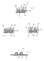
- the guide grooves in the underside of the application head can have 20 different shapes; two guide grooves 22a with a semicircular cross section are shown in FIG. 2, two guide grooves 22b with a rectangular cross section are shown in FIG. 3, and two guide grooves 22c with a triangular cross section are shown in FIG.
- FIGS. 2 to 4 also show the outlet slots 24a (FIG. 2), 24b (FIG. 3) and 24c (FIG. 4) and a plurality of feed openings 26a (FIG. 2), 26b (FIG. 3) and 26c (FIG. 4) for the adhesive indicated in each guide groove 22a, 22b and 22c.
- the polyethylene web 14 is passed under the underside of the application head 20 at a short distance, which should be a maximum of 2 mm.
- the threads 18 run individually through the corresponding guide grooves 22a (FIG. 2), 22b (FIG. 3) or 22c (FIG. 4), so that the threads 18 are enveloped uniformly from all sides by the adhesive 28 indicated by the hatched area, which emerges from the slots 24a, 24b and 24c and the openings 26a, 26b and 26c.
- Each thread 18 is therefore embedded in an adhesive tube which forms between the guide groove and the polyethylene web 14.
- the adhesive supply is clocked, so that only short pieces of thread are provided with the adhesive, as can be seen in FIG. 1, where the individual adhesive areas on the threads 18 are indicated by the reference numerals 30.
- the threads 18 coated with the adhesive 28 come either directly below the application head 20 or, viewed in the transport direction, just behind the application head 20 into contact with the polyethylene web 14 and are then fed together to the roller 12, where the nonwoven web 16 is on the top the polyethylene web 14 is laminated on; as a result, the elastic threads 18 provided with the adhesive are located between the nonwoven web 16 and the polyethylene web 14.
- FIG. 5 shows two elastic threads 18, the polyethylene web 14, the nonwoven web 16 and the adhesive 28 which connects the threads 18 to the two webs 14, 16.
- the threads 18 have a relatively large play in semicircular or rectangular guide grooves, so that they can be displaced in the guide grooves by the hydraulic effect of the adhesive and thus coated unevenly.
- FIG. 4 A preferred embodiment is therefore shown in FIG. 4, namely guide grooves 22c, which have the shape of an isosceles, in particular equilateral triangle in cross section.
- the feed openings 26c for the adhesive are located at the three corners of the triangle, in order in this way to ensure a uniform coating of the elastic threads 18 over their entire surface.
Abstract
Description
Die Erfindung betrifft eine Vorrichtung zum Auftragen eines Klebstoffes auf elastische Fäden der im Oberbegriff des Anspruchs 1 angegebenen Gattung.The invention relates to a device for applying an adhesive to elastic threads of the type specified in the preamble of claim 1.
Sich bei Erwärmung kräuselnde, bahnförmige Flächengebilde werden insbesondere als elastische Bünde für Wegwerfkleidung, bspw. für kerntechnische Anlagen, aber auch bei elastischen Binden, Verbänden und Hygienen-Artikeln, wie bspw. Windeln, eingesetzt, um dichte, jedoch elastisch verformbare Abschlüsse zu erzielen.Rippled, sheet-like structures when heated are used in particular as elastic bundles for disposable clothing, for example for nuclear facilities, but also for elastic bandages, bandages and hygiene articles, such as diapers, in order to achieve tight, but elastically deformable closures.
Der Grundaufbau eines solchen Flächengebildes geht bspw. aus der US-PS 4 640 859 hervor und weist ein Substrat sowie in einen Klebstoff eingebettete, vorgereckte Elastomorfäden auf, nämlich sogenannte "Spandex-Fasern", also Polyurethan-Elastomerfasern.The basic structure of such a flat structure is evident, for example, from US Pat. No. 4,640,859 and has a substrate and pre-stretched elastomer threads embedded in an adhesive, namely so-called “spandex fibers”, that is to say polyurethane elastomer fibers.
Bei den bekannten Flächengebilde werden Filme bzw. Folien aus einem unelastischen, thermoplastischen Polymer, insbesondere auf der Basis von Ethylenvinylacetat (EVA)-Copolymeren verwendet, die von beiden Seiten auf die vorgereckten Elastomerfäden auflaminiert werden. Das Auflaminieren erfolgt unter Erwärmung, wobei die Wärmeenergie über eine Heizwalze zugeführt wird; anschließend muß das Laminat wieder gekühlt werden, um das Ausreagieren des Klebstoffes zu unterbrechen.In the known flat structures, films or foils made of an inelastic, thermoplastic polymer, in particular based on ethylene vinyl acetate (EVA) copolymers, are used, which are laminated onto the pre-stretched elastomer threads from both sides. The lamination takes place with heating, the thermal energy being supplied via a heating roller; the laminate must then be cooled again in order to interrupt the reaction of the adhesive.
Die Herstellung dieses Flächengebildes ist wegen der Erwärmung und des anschließend Abkühlens des Klebstoffes sehr aufwendig; außerdem müssen Klebstoffolien verwendet werden, die sehr kostspielig und in der Handhabung kompliziert sind.The production of this fabric is very complex because of the heating and then cooling of the adhesive; In addition, adhesive films have to be used, which are very expensive and complicated to handle.
Weiterhin geht aus dem DE-GM 88 06 965 eine Vorrichtung zur Herstellung eines solchen Flächengebildes hervor, bei der mittels eines Schmelzgerätes zumindest partiell eine Schmelzkleberschicht auf das abgewickelte Substrat oder auf die elastischen Fäden aufgebracht wird. Dabei kann der zugehörige Auftragkopf mit einer Schmelzdüse oder einer Sprühdüse für das Aufbringen des Schmelzklebers versehen sein.Furthermore, DE-GM 88 06 965 discloses a device for producing such a flat structure, in which a melt adhesive layer is at least partially applied to the unwound substrate or to the elastic threads by means of a melting device. The associated application head can be provided with a melt nozzle or a spray nozzle for applying the hot melt adhesive.
Schließlich wird in der DE-PS 37 07 349 ein Verfahren zum dauerhaften Verbinden von dehnbaren faden- oder bändchenförmigen Elementen auf einem flächigen Substrat beschrieben, bei dem das auf dem flächigen Substrat angeordnete bzw. fixierte faden- oder bändchenförmige Element mit einem versprühten Schmelzklebstoff abgedeckt oder besprüht wird; dabei befaßt der Schmelzklebstoff auch die Nachbarbereiche des faden- oder bändchenförmigen Elementes, also die angrenzenden Substratbereiche, so daß der Schmelzklebstoff-Verbrauch relativ hoch wird, da sich auch auf den Bereichen zwischen den Fäden, die für die Verklebung ansich nicht benötigt werden, Schmelzklebstoff befindet.Finally, DE-PS 37 07 349 describes a method for permanently connecting stretchable thread-like or ribbon-like elements on a flat substrate, in which the thread-like or ribbon-like element arranged or fixed on the flat substrate is covered with a sprayed hot melt adhesive or is sprayed; the hot melt adhesive also affects the neighboring areas of the thread-like or ribbon-like element, that is to say the adjacent substrate areas, so that the hot melt adhesive consumption becomes relatively high, since hot melt adhesive is also located on the areas between the threads which are not required for the bonding itself .
Der Erfindung liegt deshalb die Aufgabe zugrunde, eine Vorrichtung zum Auftragen eines Schmelzklebstoffes auf elastische Fäden der angegebenen Gattung zu schaffen, bei der die oben erwähnten Nachteile nicht auftreten. Insbesondere soll eine Auftragvorrichtung vorgeschlagen werden, die im Vergleich mit den bisher üblichen Ausführungsformen eine relevante Klebstoff-Einsparung ermöglicht.The invention is therefore based on the object of providing a device for applying a hot melt adhesive to elastic threads of the type specified, in which the disadvantages mentioned above do not occur. In particular, an application device is to be proposed which, in comparison with the previously customary embodiments, enables relevant adhesive savings.
Dies wird erfindungsgemäß durch die im kennzeichnenden Teil des Anspruchs 1 angegebenen Merkmale erreicht.This is achieved according to the invention by the features specified in the characterizing part of claim 1.
Zweckmäßige Ausführungsformen werden durch die Merkmale der Unteransprüche beschrieben.Appropriate embodiments are described by the features of the subclaims.
Die mit der Erfindung erzielten Vorteile beruhen darauf, daß zum Zeitpunkt des Aufbringens des Klebstoffes die elastischen Fäden sehr exakt geführt und damit positioniert sind, so daß der Klebstoff gezielt auf die Fäden und nicht auf die Flächenbereiche zwischen den einzelnen Fäden aufgebracht werden kann. Dadurch läßt sich im Vergleich mit den herkömmlichen Techniken eine Klebstoff-Einsparung von 30 bis 40 % erzielen.The advantages achieved with the invention are based on the fact that at the time of applying the adhesive, the elastic threads are guided and positioned very precisely, so that the adhesive can be applied specifically to the threads and not to the surface areas between the individual threads. In this way, an adhesive saving of 30 to 40% can be achieved in comparison with the conventional techniques.
Gleichzeitig wird gewährleistet, daß die Fäden gleichmäßig auf ihrer gesamten Oberfläche mit dem Klebstoff versehen werden, wie es für die erforderliche, hoch beanspruchbare Verbindung zwischen den Fäden und den entsprechenden Substraten für die Herstellung von Hygiene-Artikeln, bspw. von Windeln, notwendig ist.At the same time, it is ensured that the threads are provided with the adhesive evenly over their entire surface, as is necessary for the required, highly stressable connection between the threads and the corresponding substrates for the production of hygiene articles, for example diapers.
Werden gefärbte Klebstoffe verwendet, so können die mit dem Klebstoff beschichteten elastischen Fäden optisch gekennzeichnet werden; damit läßt sich eine zusätzliche Qualitätskontrolle realisieren, indem bspw. verschiedene Faden-Typen entsprechend unterschiedlich gefärbten Klebstoffen zugeordnet werden, man also an der Färbung sofort erkennen kann, ob es sich um eine bestimmte Type handelt.If colored adhesives are used, the elastic threads coated with the adhesive can be optically identified; This enables an additional quality control to be implemented, for example by assigning different thread types to differently colored adhesives, so that one can immediately see from the coloring whether it is a specific type.
Und schließlich ergibt sich auch eine vergleichsweise geringe thermische Belastung der in der Regel vorgereckten und damit besonders empfindlichen elastischen Fäden; dies beruht zunächst darauf, daß mit einer minimalen Menge an erwärmten Klebstoff gearbeitet werden kann, so daß auch nur eine entsprechend geringe Wärmemenge auf die Fäden übertragen wird.And finally there is also a comparatively low thermal load on the usually pre-stretched and thus particularly sensitive elastic threads; This is based first of all on the fact that a minimal amount of heated adhesive can be used, so that only a correspondingly small amount of heat is transferred to the threads.
Außerdem kann der Auftragkopf nun in unmittelbarer Nähe des mit den Fäden zu beschichtenden Substrates angeordnet werden, so daß die von dem warmen Klebstoff ausgehende Wärme über die Fäden sofort auf das zu beschichtende Substrat abgeleitet wird.In addition, the application head can now be arranged in the immediate vicinity of the substrate to be coated with the threads, so that the heat emanating from the warm adhesive is immediately dissipated via the threads to the substrate to be coated.
Zu diesem Zweck wird nach einer bevorzugten Ausführungsform der Auftragkopf in einem Abstand von maximal 2 mm über der zu beschichtenden Warenbahn, bspw. einer Polyethylen-Bahn bei der Herstellung von Windeln, angeordnet, wobei sogar bei mechanischem Kontakt zwischen Bahn und Auftragkopf die einwandfreie Beschichtung der einzelnen Fäden, die sich in den Führungsnuten des Auftragkopfs befinden, möglich ist.For this purpose, according to a preferred embodiment, the application head is arranged at a maximum distance of 2 mm above the material web to be coated, for example a polyethylene web in the manufacture of diapers, the perfect coating of the even with mechanical contact between the web and application head individual threads, which are located in the guide grooves of the application head, is possible.
Die Führungsnuten können im Prinzip beliebige Querschnitte haben, also bspw. Halbkreis- oder Rechteck-Formen. Insbesondere bei hohen Fadengeschwindigkeiten besteht jedoch die Gefahr, daß die Fäden durch den "Hydraulikeffekt" des Klebstoffes in solchen Führungsnuten von einer Seite auf die andere Seite gedrückt und dadurch ungleichmäßig beschichtet werden.In principle, the guide grooves can have any cross sections, for example semicircular or rectangular shapes. Particularly at high thread speeds, however, there is a risk that the threads will be pressed from one side to the other side by the "hydraulic effect" of the adhesive in such guide grooves and thereby coated unevenly.
Aus diesem Grund werden nach einer bevorzugten Ausführungsform Führungsnuten verwendet, die im Querschnitt die Form eines gleichschenkligen, insbesondere gleichseitigen Dreiecks haben, da sich hierdurch eine selbsttätige Zentrierung der Elastikfäden in den dreieckigen Führungsnuten ergibt.For this reason, according to a preferred embodiment, guide grooves are used which have the shape of an isosceles, in particular equilateral triangle in cross section, since this results in an automatic centering of the elastic threads in the triangular guide grooves.
Gleichzeitig läßt sich mit solchen dreieckigen Führungsnuten noch eine sehr gleichmäßige Beschichtung der Elastikfäden mit dem Klebstoff realisieren, indem die Zuführöffnungen für den Klebstoff an den drei Ecken des Dreiecks angeordnet werden.At the same time, with such triangular guide grooves, a very uniform coating of the elastic threads with the adhesive can be achieved by arranging the feed openings for the adhesive at the three corners of the triangle.
Die Erfindung wird im folgenden anhand von Ausführungsbeispielen unter Bezugnahme auf die beiliegenden, schematischen Zeichnungen näher erläutert. Es zeigen
- Fig. 1 eine perspektivische Schema-Darstellung einer Vorrichtung zur Herstellung eines sich bei Erwärmung kräuselnden Flächengebildes mit einer integrierten Vorrichtung zum Auftragen eines Klebstoffes auf die hierbei verwendeten, elastischen Fäden,
- Fig. 2 eine Schnittdarstellung des Details X von Figur 1,
- Fig. 3 eine Figur 2 entsprechende Schnittansicht einer weiteren Ausführungsform der Führungsnuten,
- Fig. 4 eine Figur 2 entsprechende Schnittansicht einer dritten Ausführungsform der Führungsnuten, und
- Fig. 5 eine Schnittansicht des Details Y von Figur 1.
- 1 is a perspective schematic representation of a device for producing a sheet that curls when heated with an integrated device for applying an adhesive to the elastic threads used here,
- 2 shows a sectional illustration of the detail X from FIG. 1,
- 3 shows a sectional view corresponding to FIG. 2 of a further embodiment of the guide grooves,
- Fig. 4 is a sectional view corresponding to Figure 2 of a third embodiment of the guide grooves, and
- 5 shows a sectional view of the detail Y from FIG. 1.
Die aus Figur 1 ersichtliche, allgemein durch das Bezugszeichen 10 angedeutete Vorrichtung zur Herstellung eines sich bei Erwärmung kräuselnden Flächengebildes, wie es bspw. für Hygiene-Artikel verwendet wird, weist eine drehbare Walze 12 auf, der eine Polyethylen-Bahn 14, eine Vliesstoffbahn 16 und vorgereckte Elastikfäden 18 jeweils in Richtung der Pfeile zugeführt und dadurch miteinander verbunden werden.The device shown in FIG. 1, generally indicated by the
In Transportrichtung der Polyethylen-Bahn 14 gesehen vor der Walze 12 befindet sich ein Auftragkopf 20, dem von einer Klebstoffquelle (nicht dargestellt) ein verflüssigter und damit fließfähiger Klebstoff, insbesondere ein Schmelzklebstoff, zugeführt wird.In the transport direction of the
Die Unterseite des Auftragkopfes 20 befindet sich in einem Abstand von maximal 2 mm über der Oberseite der Polyethylen-Bahn 14.The underside of the
Wie man aus den Schnittansichten des Details X von Figur 1 in den Figuren 2 bis 4 erkennen kann, ist der Auftragkopf 20 an seiner Unterseite mit Führungsnuten für die Fäden 18 versehen. Diese Führungsnuten sind im Querschnitt etwas größer als die Fäden 18, so daß die Fäden 18 weitgehend in den Führungsnuten aufgenommen werden und nach unten nur etwas über die Unterseite des Auftragkopfes 20 hinaus vorstehen.As can be seen from the sectional views of the detail X of FIG. 1 in FIGS. 2 to 4, the
Wie man aus den Figuren 2 bis 4 erkennt, können die Führungsnuten in der Unterseite des Auftragkopfes 20 verschiedene Formen haben; so sind in Figur 2 zwei Führungsnuten 22a mit halbkreisförmigem Querschnitt, in Figur 3 zwei Führungsnuten 22b mit rechteckigem Querschnitt und in Figur 4 zwei Führungsnuten 22c mit dreieckigem Querschnitt dargestellt.As can be seen from FIGS. 2 to 4, the guide grooves in the underside of the application head can have 20 different shapes; two
In den Figuren 2 bis 4 sind außerdem die Austrittsschlitze 24a (Figur 2), 24b (Figur 3) und 24c (Figur 4) sowie mehrere Zuführöffnungen 26a (Figur 2), 26b (Figur 3) und 26c (Figur 4) für den Klebstoff in jeder Führungsnut 22a, 22b und 22c angedeutet.FIGS. 2 to 4 also show the
Wie man aus den Figuren 1 bis 4 erkennt, wird die Polyethylen-Bahn 14 in einem geringen Abstand, der maximal 2 mm betragen sollte, unter der Unterseite des Auftragkopfes 20 hindurchgeführt. Gleichzeitig verlaufen die Fäden 18 einzeln durch die entsprechenden Führungsnuten 22a (Figur 2), 22b (Figur 3) oder 22c (Figur 4), so daß die Fäden 18 von allen Seiten gleichmäßig von dem durch die schraffierte Fläche angedeuten Klebstoff 28 umhüllt werden, der aus den Schlitzen 24a, 24b bzw. 24c und den Öffnungen 26a, 26b bzw. 26c austritt. Jeder Faden 18 ist also in einen Klebstoff-Schlauch eingebettet, der sich zwischen der Führungsnut und der Polyethylen-Bahn 14 ausbildet.As can be seen from FIGS. 1 to 4, the
Die Klebstoffzufuhr erfolgt getaktet, so daß jeweils nur kurze Faden-Stücke mit dem Klebstoff versehen werden, wie man in Figur 1 erkennt, wo die einzelnen Klebstoff-Bereiche auf den Fäden 18 durch die Bezugszeichen 30 angedeutet sind.The adhesive supply is clocked, so that only short pieces of thread are provided with the adhesive, as can be seen in FIG. 1, where the individual adhesive areas on the
Die mit dem Klebstoff 28 beschichteten Fäden 18 gelangen entweder direkt unterhalb des Auftragkopfes 20 oder in Transportrichtung gesehen kurz hinter dem Auftragkopf 20 in Kontakt mit der Polyethylen-Bahn 14 und werden dann gemeinsam der Walze 12 zugeführt, wo die Vliesstoff-Bahn 16 auf die Oberseite der Polyethylen-Bahn 14 aufkaschiert wird; dadurch befinden sich die mit dem Klebstoff versehenen elastischen Fäden 18 zwischen der Vliesstoff-Bahn 16 und der Polyethylen-Bahn 14.The
Der sich ergebene Sandwich-Aufbau ist aus Figur 5 zu erkennen, die zwei elastische Fäden 18, die Polyethylen-Bahn 14, die Vliesstoff-Bahn 16 sowie den Klebstoff 28 zeigt, der die Fäden 18 mit den beiden Bahnen 14, 16 verbindet.The resulting sandwich structure can be seen in FIG. 5, which shows two
Wie man aus den Figuren 2 und 3 erkennt, haben die Fäden 18 in halbkreisförmigen oder rechteckigen Führungsnuten ein relativ großes Spiel, so daß sie durch den Hydraulikeffekt des Klebstoffes in den Führungsnuten verschoben und damit ungleichmäßig beschichtet werden können.As can be seen from FIGS. 2 and 3, the
Eine bevorzugte Ausführungsform stellt deshalb Figur 4 dar, nämlich Führungsnuten 22c, die im Querschnitt die Form eines gleichschenkligen, insbesondere gleichseitigen Dreiecks haben. Dabei befinden sich die Zuführöffnungen 26c für den Klebstoff an den drei Ecken des Dreieckes, um auf diese Weise eine gleichmäßige Beschichtung der elastischen Fäden 18 auf ihrer gesamten Oberfläche zu gewährleisten.A preferred embodiment is therefore shown in FIG. 4, namely
Claims (9)
a) mit einem Auftragkopf, und
b) mit Auslaßöffnungen für den Klebstoff in dem Auftragkopf, dadurch gekennzeichnet, daß
c) der Auftragkopf (20) Führungsnuten (22a, 22b, 22c) für die einzelnen Fäden (18) aufweist, und daß
d) in jeder Führungsnut (22a, 22b, 22c) mindestens eine Auslaßöffnung (26a, 26b, 26c) für den Klebstoff (28) mündet.1. Device for applying an adhesive to elastic threads
a) with an application head, and
b) with outlet openings for the adhesive in the application head, characterized in that
c) the application head (20) has guide grooves (22a, 22b, 22c) for the individual threads (18), and that
d) at least one outlet opening (26a, 26b, 26c) for the adhesive (28) opens into each guide groove (22a, 22b, 22c).
Applications Claiming Priority (2)
| Application Number | Priority Date | Filing Date | Title |
|---|---|---|---|
| DE8815242U | 1988-12-07 | ||
| DE8815242U DE8815242U1 (en) | 1988-12-07 | 1988-12-07 |
Publications (2)
| Publication Number | Publication Date |
|---|---|
| EP0372120A2 true EP0372120A2 (en) | 1990-06-13 |
| EP0372120A3 EP0372120A3 (en) | 1990-08-01 |
Family
ID=6830563
Family Applications (1)
| Application Number | Title | Priority Date | Filing Date |
|---|---|---|---|
| EP88121253A Withdrawn EP0372120A3 (en) | 1988-12-07 | 1988-12-19 | Device for applying glue to elastic threads |
Country Status (2)
| Country | Link |
|---|---|
| EP (1) | EP0372120A3 (en) |
| DE (1) | DE8815242U1 (en) |
Cited By (6)
| Publication number | Priority date | Publication date | Assignee | Title |
|---|---|---|---|---|
| US7578882B2 (en) | 2003-01-22 | 2009-08-25 | Nordson Corporation | Module, nozzle and method for dispensing controlled patterns of liquid material |
| US7647885B2 (en) | 2002-04-12 | 2010-01-19 | Nordson Corporation | Module, nozzle and method for dispensing controlled patterns of liquid material |
| WO2014085117A1 (en) * | 2012-11-27 | 2014-06-05 | The Procter & Gamble Company | Method and apparatus for applying an elastic material to a moving substrate in a curved path |
| US9248054B2 (en) | 2012-11-27 | 2016-02-02 | The Procter & Gamble Company | Methods and apparatus for making elastic laminates |
| US9265672B2 (en) | 2012-11-27 | 2016-02-23 | The Procter & Gamble Company | Methods and apparatus for applying adhesives in patterns to an advancing substrate |
| US9682392B2 (en) | 2012-04-11 | 2017-06-20 | Nordson Corporation | Method for applying varying amounts or types of adhesive on an elastic strand |
Citations (2)
| Publication number | Priority date | Publication date | Assignee | Title |
|---|---|---|---|---|
| EP0095034A1 (en) * | 1982-04-14 | 1983-11-30 | Uni-Charm Corporation | Method for the manufactureof a disposable diaper |
| EP0115286A1 (en) * | 1983-01-19 | 1984-08-08 | BOUSSAC SAINT FRERES B.S.F. Société anonyme dite: | Method of making disposable diapers and diapers produced by this method |
Family Cites Families (5)
| Publication number | Priority date | Publication date | Assignee | Title |
|---|---|---|---|---|
| FR1502746A (en) * | 1966-08-03 | 1967-11-24 | Rhodiaceta | Method and device for the treatment, with liquid, of moving threads or bands |
| US3762142A (en) * | 1970-03-03 | 1973-10-02 | O Rasmussen | Yarnlike product kept together by circumjacent polymer material, and a method and an apparatus for producing said product |
| JPS515113B1 (en) * | 1971-06-14 | 1976-02-17 | ||
| CH632118B (en) * | 1980-07-09 | Heberlein & Co Ag | PROCESS AND DEVICE FOR WETTING AND SUBSEQUENT TEXTURING OF TEXTILE YARNS. | |
| DE3701941A1 (en) * | 1987-01-23 | 1988-08-04 | Dittberner Gmbh | ORDER HEAD |
-
1988
- 1988-12-07 DE DE8815242U patent/DE8815242U1/de not_active Expired - Lifetime
- 1988-12-19 EP EP88121253A patent/EP0372120A3/en not_active Withdrawn
Patent Citations (2)
| Publication number | Priority date | Publication date | Assignee | Title |
|---|---|---|---|---|
| EP0095034A1 (en) * | 1982-04-14 | 1983-11-30 | Uni-Charm Corporation | Method for the manufactureof a disposable diaper |
| EP0115286A1 (en) * | 1983-01-19 | 1984-08-08 | BOUSSAC SAINT FRERES B.S.F. Société anonyme dite: | Method of making disposable diapers and diapers produced by this method |
Cited By (13)
| Publication number | Priority date | Publication date | Assignee | Title |
|---|---|---|---|---|
| US7647885B2 (en) | 2002-04-12 | 2010-01-19 | Nordson Corporation | Module, nozzle and method for dispensing controlled patterns of liquid material |
| US9855583B2 (en) | 2002-04-12 | 2018-01-02 | Nordson Corporation | Method for dispensing controlled patterns of liquid material |
| US8800477B2 (en) | 2002-04-12 | 2014-08-12 | Nordson Corporation | Module, nozzle and method for dispensing controlled patterns of liquid material |
| US7578882B2 (en) | 2003-01-22 | 2009-08-25 | Nordson Corporation | Module, nozzle and method for dispensing controlled patterns of liquid material |
| US9682392B2 (en) | 2012-04-11 | 2017-06-20 | Nordson Corporation | Method for applying varying amounts or types of adhesive on an elastic strand |
| US9265672B2 (en) | 2012-11-27 | 2016-02-23 | The Procter & Gamble Company | Methods and apparatus for applying adhesives in patterns to an advancing substrate |
| US9248054B2 (en) | 2012-11-27 | 2016-02-02 | The Procter & Gamble Company | Methods and apparatus for making elastic laminates |
| US9295590B2 (en) | 2012-11-27 | 2016-03-29 | The Procter & Gamble Company | Method and apparatus for applying an elastic material to a moving substrate in a curved path |
| CN104812346A (en) * | 2012-11-27 | 2015-07-29 | 宝洁公司 | Method and apparatus for applying an elastic material to a moving substrate in a curved path |
| US9730839B2 (en) | 2012-11-27 | 2017-08-15 | The Procter & Gamble Company | Method and apparatus for applying an elastic material to a moving substrate in a curved path |
| US9808827B2 (en) | 2012-11-27 | 2017-11-07 | The Procter & Gamble Company | Methods and apparatus for applying adhesives in patterns to an advancing substrate |
| WO2014085117A1 (en) * | 2012-11-27 | 2014-06-05 | The Procter & Gamble Company | Method and apparatus for applying an elastic material to a moving substrate in a curved path |
| US10729593B2 (en) | 2012-11-27 | 2020-08-04 | The Procter & Gamble Company | Methods and apparatus for making elastic laminates |
Also Published As
| Publication number | Publication date |
|---|---|
| EP0372120A3 (en) | 1990-08-01 |
| DE8815242U1 (en) | 1990-05-10 |
Similar Documents
| Publication | Publication Date | Title |
|---|---|---|
| DE3308015C3 (en) | Process for incorporating elastic parts into a disposable diaper | |
| DE60027236T2 (en) | Disposable diaper with patterned layer and process for its preparation | |
| EP0510715B1 (en) | Process for attaching elastic elements around the leg openings of disposable clothing | |
| DE3521374C2 (en) | ||
| DE69838982T2 (en) | DISPOSABLE TROUSERS AND METHOD FOR CONTINUOUS MANUFACTURE | |
| DE69333595T2 (en) | Method and apparatus for controlling a jet of liquid to create a pattern | |
| DE19730181C2 (en) | Absorbent composite product with a liquid absorption base layer | |
| DE2836714C3 (en) | Coating head for multiple strip coating | |
| DE2649039A1 (en) | RELATED ONE-PIECE DISPOSABLE DIAPER AND METHOD OF MANUFACTURING IT | |
| EP0330716A2 (en) | Heat-shirring sheet structure and method and apparatus for its manufacture | |
| DE3739962A1 (en) | LIQUID-OPPERABLE MULTIPLE-LAYER MATERIAL AND METHOD FOR THE PRODUCTION THEREOF | |
| DE3004332A1 (en) | METHOD FOR PRODUCING A RAIL-SHAPED COMPOSITE BODY | |
| EP0380781A2 (en) | Device for applying glue to elastic threads | |
| EP0565718B1 (en) | Flexible plastic sheet having rib structure | |
| DE60021662T2 (en) | A liquid-permeable cover sheet for a disposable absorbent article and method of making the same | |
| EP0372120A2 (en) | Device for applying glue to elastic threads | |
| EP0052321A1 (en) | Heat exchange element of flexible material | |
| WO2021224050A1 (en) | Laminating installation | |
| DE3900619C2 (en) | ||
| EP0315013A2 (en) | Sanitary article and method of manufacturing a sanitary article | |
| DE69629476T2 (en) | MANUFACTURING METHOD FOR A HEAT INSULATION STRUCTURE | |
| WO1997009180A1 (en) | Transfer foil for printing on objects and objects printed therewith | |
| DE3235151A1 (en) | Device for applying several layers of adhesive to a carrier when manufacturing self-adhesive tapes | |
| JPH02289165A (en) | Apparatus for applying adhesive to elastic string | |
| DE19647458A1 (en) | Multilayered non=woven for sanitary wear |
Legal Events
| Date | Code | Title | Description |
|---|---|---|---|
| PUAI | Public reference made under article 153(3) epc to a published international application that has entered the european phase |
Free format text: ORIGINAL CODE: 0009012 |
|
| PUAL | Search report despatched |
Free format text: ORIGINAL CODE: 0009013 |
|
| AK | Designated contracting states |
Kind code of ref document: A2 Designated state(s): AT BE CH DE ES FR GB GR IT LI LU NL SE |
|
| AK | Designated contracting states |
Kind code of ref document: A3 Designated state(s): AT BE CH DE ES FR GB GR IT LI LU NL SE |
|
| STAA | Information on the status of an ep patent application or granted ep patent |
Free format text: STATUS: THE APPLICATION HAS BEEN WITHDRAWN |
|
| 18W | Application withdrawn |
Withdrawal date: 19901227 |
|
| R18W | Application withdrawn (corrected) |
Effective date: 19901227 |